


- Improving ceramic monolith properties in binder jetting 3D printing using glass frit binders
Jung-Hoon Choia,b, Kyu-Hong Hwanga, Ung-Soo Kimb, Ji-Hyeon Leeb, Kwang-Bo Shimc, Seung-Min Kangd and Woo-Seok Chob*
aDepartment of Materials Science and Engineering, Gyeongsang National University, 501, Jinju-daero, Jinju-si, Gyeongsangnam-do, Korea
bKorea Institute of Ceramic Engineering and Technology, 3321 Gyeongchung-daero, Sindun-myeon, Icheon-si, Gyeonggi-do, Korea
cDepartment of Materials Science and Engineering, Hanyang University, Seoul 04763, Korea
dDepartment of Advanced Materials Science and Engineering, Hanseo University, Seosan, Korea
In this study, a glass frit binder capable of replacing liquid binders was applied to improve the density of the object manufactured by the binder jetting 3D printing technology. To secure easy ejection from the inkjet head, the viscosity, surface tension, and stability of the glass frit binder were selected as important factors and their optimal values were determined. Of the seven dispersants tested, 0.8 mg/m2 of Na-polyacrylic acid with a molecular weight of 8100 g/mol resulted in the best dispersion characteristics. The optimal surface tension was confirmed when 1.0 wt% of polysiloxane was added. The stability of the slurry improved and the role of the binder was induced on adding 6 wt% of polyvinyl alcohol. 100×10×5 mm3 test specimens were fabricated by jetting the optimized glass frit binder to a silicate mixed powder and the density change was observed. The densities and water absorption rates of the specimens sintered at 1,200 ℃, 1,250 ℃, and 1,300 ℃were determined. The specimens fabricated with the glass frit binder exhibited approximately 19% higher density than those fabricated with a liquid binder at all temperatures. This could be because the frits in the binder melted during the firing process and filled the pores.
Keywords: Binder jetting 3D printing, Glass frit, Porcelain powder, Viscosity, Surface tension
In a previous study on manufacturing decorative porcelain figures using a binder jetting 3D printer, a ceramic product larger than 17 cm could be fabricated by applying a liquid binder to a silicate mixture bed [1]. Owing to the limitations of the binder jetting 3D printer and the raw materials used in such a process, however, improvements in the forming strength, density, and surface roughness of the specimen produced were realized in comparison with products manufactured by the existing technology.
3D printing technology, which produces a thin layer by spreading a powder and selectively injects and cures a binder solution on top of the layer, results in a low forming density because a low shear force is applied compared to that used in established ceramics manufacturing processes, such as jiggering and pressing. The low forming density also affects densification during the sintering process, thereby resulting in a low density of the final product. Moreover, owing to the limitation of the size of the raw material that can be used in a binder jetting 3D printer, the packing density is low and the surface roughness is high. To address these problems, the object is immersed in a ceramic slip after the first sintering to fill the pores with ceramic particles and then re-sintered to improve its density. This, however, causes changes in the surface resolution and complicates the process [2].
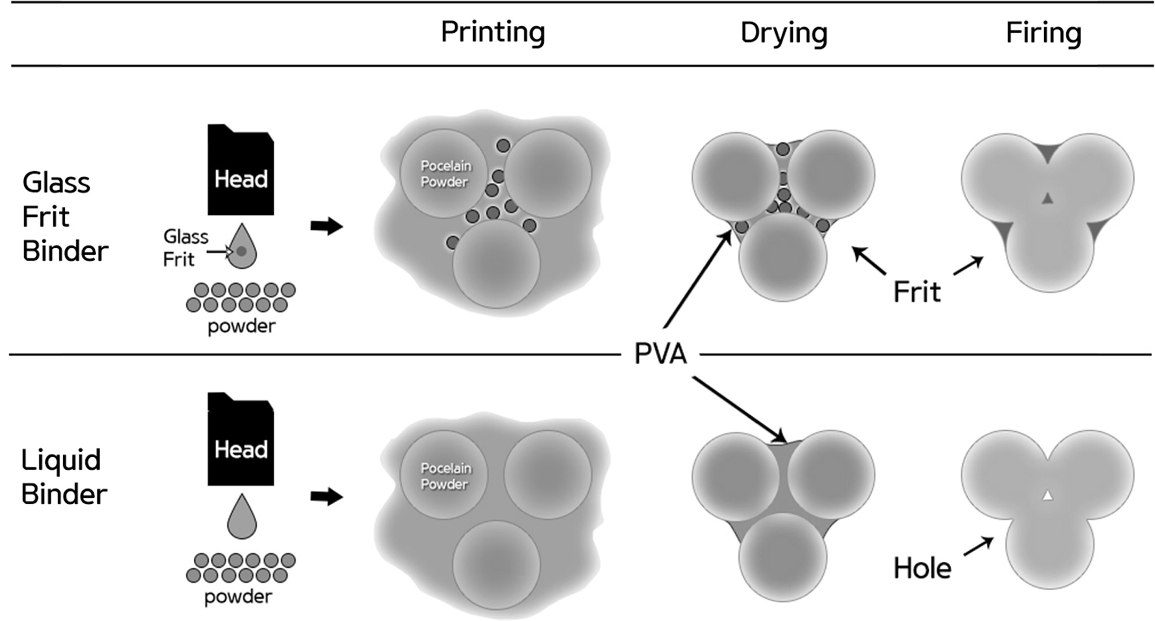
In the present study, a glass frit binder capable of replacing liquid binders was developed to improve the density of the object manufactured through the binder jetting 3D printing technology (Fig. 1). To manufacture ink applicable to binder jetting using glass frits, fluid properties such as the viscosity and surface tension must be controlled [3-5]. The viscosity of the ink is affected by the solvent used, but it is most directly affected by the amount, size, distribution, and dispersibility of the added frit. Although dispersion stabilization is possible in an aqueous system using electrostatic repulsive force, electrosteric stabilization using polymeric additive is preferred for a more stable dispersion [6]. Moreover, increasing the viscosity of the ink using a rheology modifier stabilizes the dispersibility of the particles and suppresses sedimentation of the solid [7-8]. Surface tension is involved in the process of refilling the nozzle with ink and also affects the droplet shape of the ejected ink. Water-based ink essentially has high surface tension (64 mN/m), but it has been reported that the inkjet printhead requires a surface tension in the range of 20–45 mN/m [9].
In this work, a glass frit binder that can be used in a binder jetting-type 3D printer was fabricated using glass frits, and test specimens were fabricated using the binder. The total process involved optimization of glass frit and additives, binder compliance verification, fabrication of a specimen using a binder jetting 3D printer, and sintering. The total process was compared with that using a liquid binder. The properties of the specimen formed and the sintered body that used the glass frit binder were analyzed to discuss improvements.
|
Fig. 1 Density improvement mechanism using the glass frit binder in binder jetting 3D printing. |
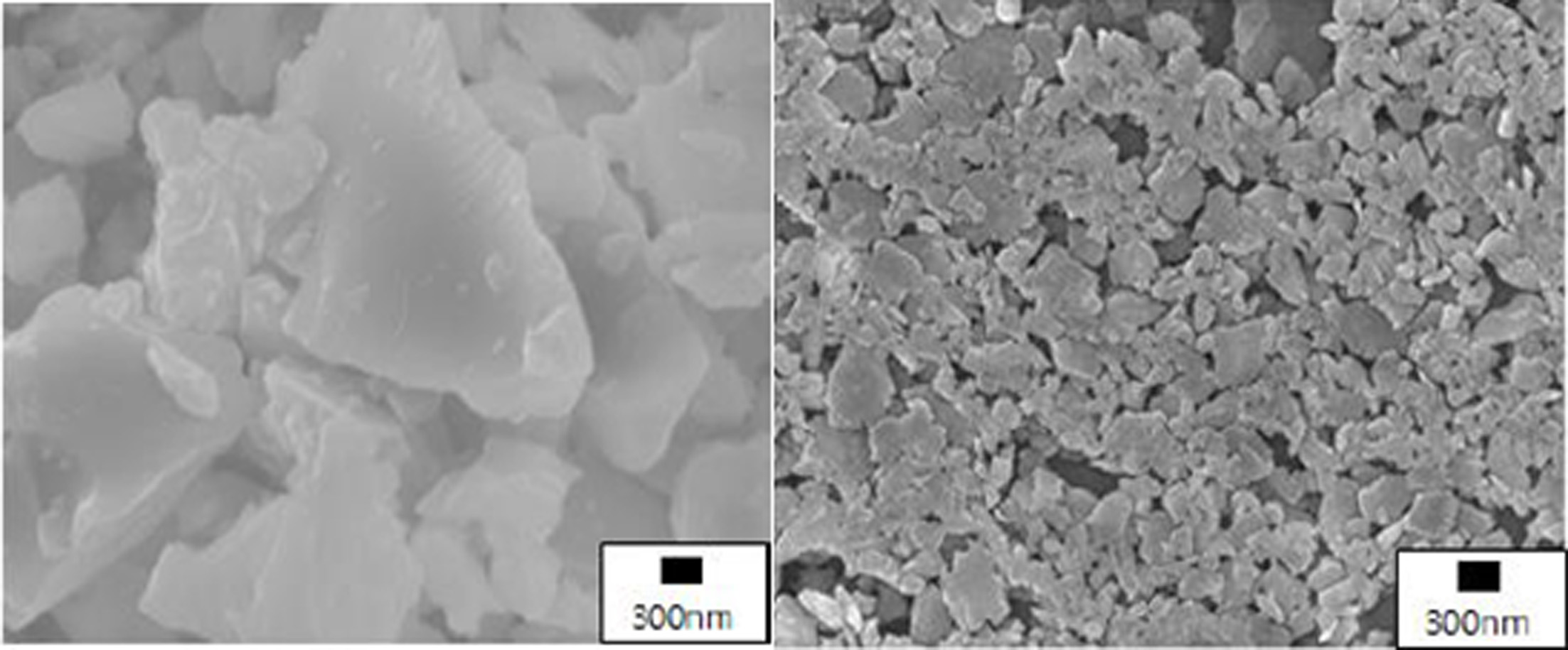
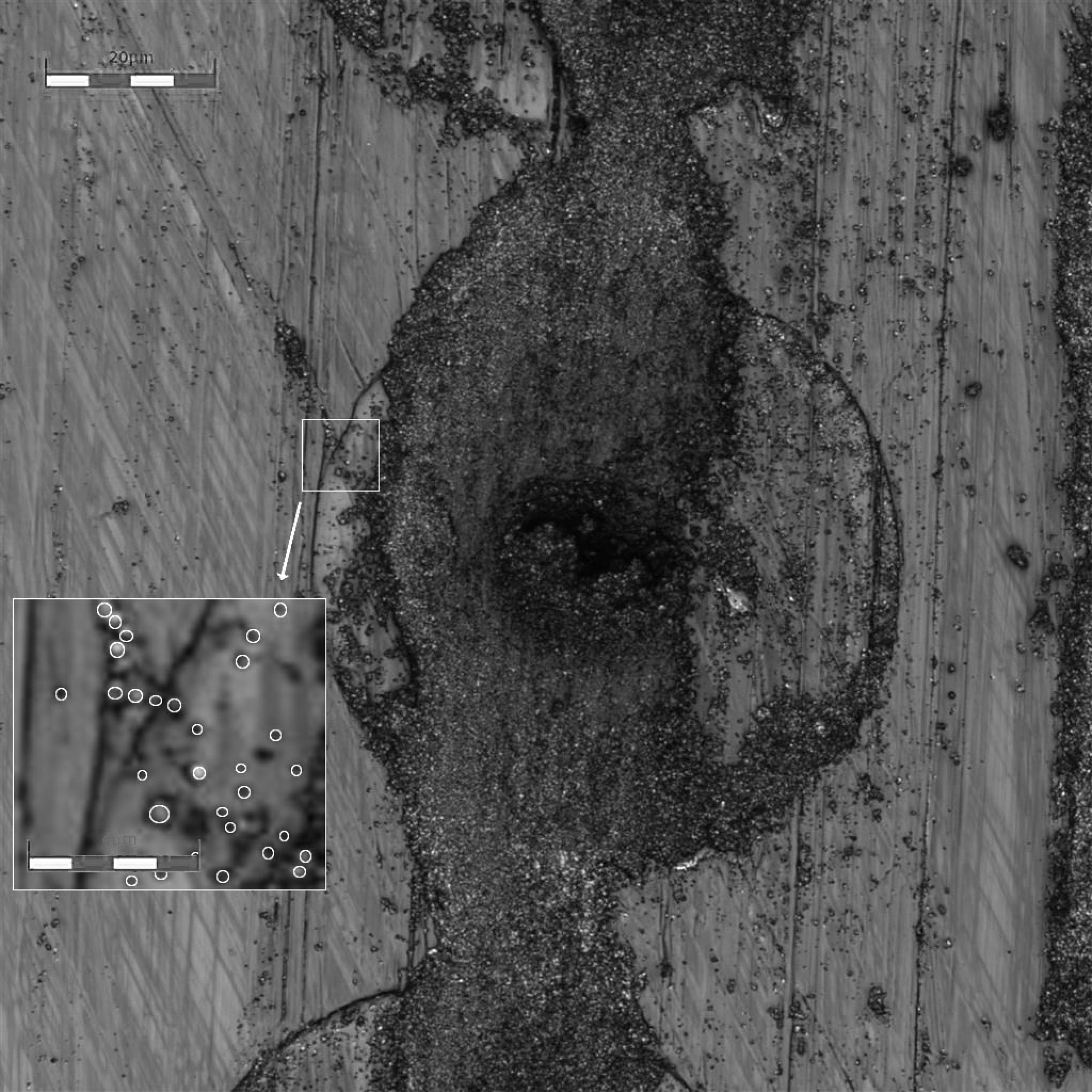
The melting point of the glass frit used in the experiment (Flux 6000, Shinceramic, Korea [average particle size = 2 μm]) was measured to be 1,050 ℃ using a high-temperature microscope. Considering the diameter (less than 100 μm) of the printhead nozzle applied to the 3D printer, the average particle size of the glass frit was reduced to 200 nm or lower using a bead mill. Fig. 2 shows the microstructures before and after milling. After milling, the density of the frit was 2.43 g/cm3 and its specific surface area was 19.1 m2/g.
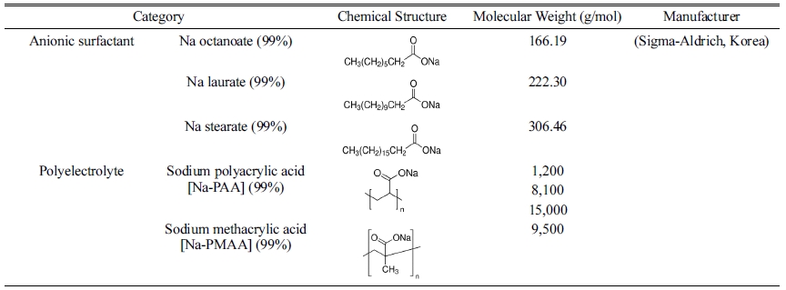
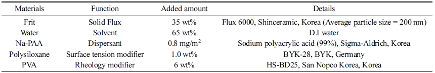
For testing the dispersibility of the glass frit in a water system, a total of seven dispersants were used: Na stearate (sodium stearate 99%, Sigma-Aldrich, Korea), Na laurate (sodium dodecanoate 99%, Sigma-Aldrich, Korea), and Na octanoate (sodium octanoate 99%, Sigma-Aldrich, Korea), which are anionic surfactants, as well as sodium polyacrylic acid [Na-PAA] (Sigma-Aldrich, Korea) with three different molecular weights and sodium methacrylic acid [Na-PMAA] (Sigma-Aldrich, Korea), which are polyelectrolytes. Each dispersant was added to distilled water in the range of 0–2.0 mg/m2 (0, 0.1, 0.2, 0.4, 0.6, 0.8, 1.0, 1.5, and 2.0 mg/m2) with respect to the specific surface area of the glass frit, and mixed for ten minutes using a sonicator. The glass frit powder was added at a content of 35 wt% and mixed for 72 h using a zirconia ball. The fabricated glass frit binder was subjected to continuous rolling after removal of the zirconia ball to prevent flocculation. The measurements were performed after 24 h to allow the binder to reach an equilibrium state. The rheological properties of the glass frit binder were examined using a rotational rheometer (HAAKE MARS III, Thermo Fisher Scientific Inc., Germany). Table 1 shows the types and characteristics of the dispersants used in the experiment.
Polysiloxane and polydimethylsiloxane (0.1, 0.5, and 1.0 wt%) were added to the frit binder with the optimal dispersant, and its surface tension was measured using a surface tension analyzer (DST-60, Surface Electro Optics Co., Korea) employing the Du Nouy Ring method. Polyvinyl alcohol (PVA, HS-BD25, San Nopco Korea, Korea) was added at 2, 4, 6, and 8 wt% with respect to the frit solids as a rheology modifier for optimal viscosity control of the frit binder. The droplet shape of the binder was observed using a drop watcher (STI Co., Korea).
Test specimens were formed by jetting the glass frit binder to a powdered mixture of clay, feldspar, and quartz developed in the previous study. The ProJet 360 model (3D SYSTEMS) was used as the binder jetting-type 3D printer. The binder jetting amount was set at 0.507 mL/cm3, which is suitable for ceramic powders, and the specimens were printed in the size 10×100×5 mm3. After drying, the specimens were sintered at a rate of 3 ℃ min-1. They were then naturally cooled after holding at the maximum temperature for 1 h. The maximum temperatures used to measure variation in the densities and water absorption rates of the specimens were 1,000, 1,100, 1,200, and 1,300 ℃ and the procedure followed was according to ASTM C373-14. The fracture surfaces of the specimens were observed using field emission scanning electron microscopy (FE-SEM, Jeol,jc JEM-6390, Japan).
|
Fig. 2 Microstructures of glass frit before (left) and after (right) crushing. |
Glass frit binder formulation
The composition of the glass frit used in the binder must be selected by considering the composition of the formed specimen and the sintering process. For a specimen composed of clay, feldspar, and quartz, the composition of the glass frit must be selected so that it can be melted at temperatures of 900–1300 ℃, the range in which the liquid phase is formed and densification is achieved. If the glass frit melts at temperatures too low or too high, poor firing density can be obtained. Moreover, the particle size of the glass frit must be adjusted according to the nozzle size of the inkjet printhead. According to literature, the particle size can range from 1/100 to 1/20 of the nozzle diameter [10-11]. This is why the chosen glass frit was milled below mean particle size of 200 nm.
To determine the optimal dispersion condition of the glass frit in a water system, rheological properties were analyzed using seven dispersants. The steady state flow of the glass frit slurry with 35% solid fabricated by varying the dispersant concentration was observed according to the share rate.
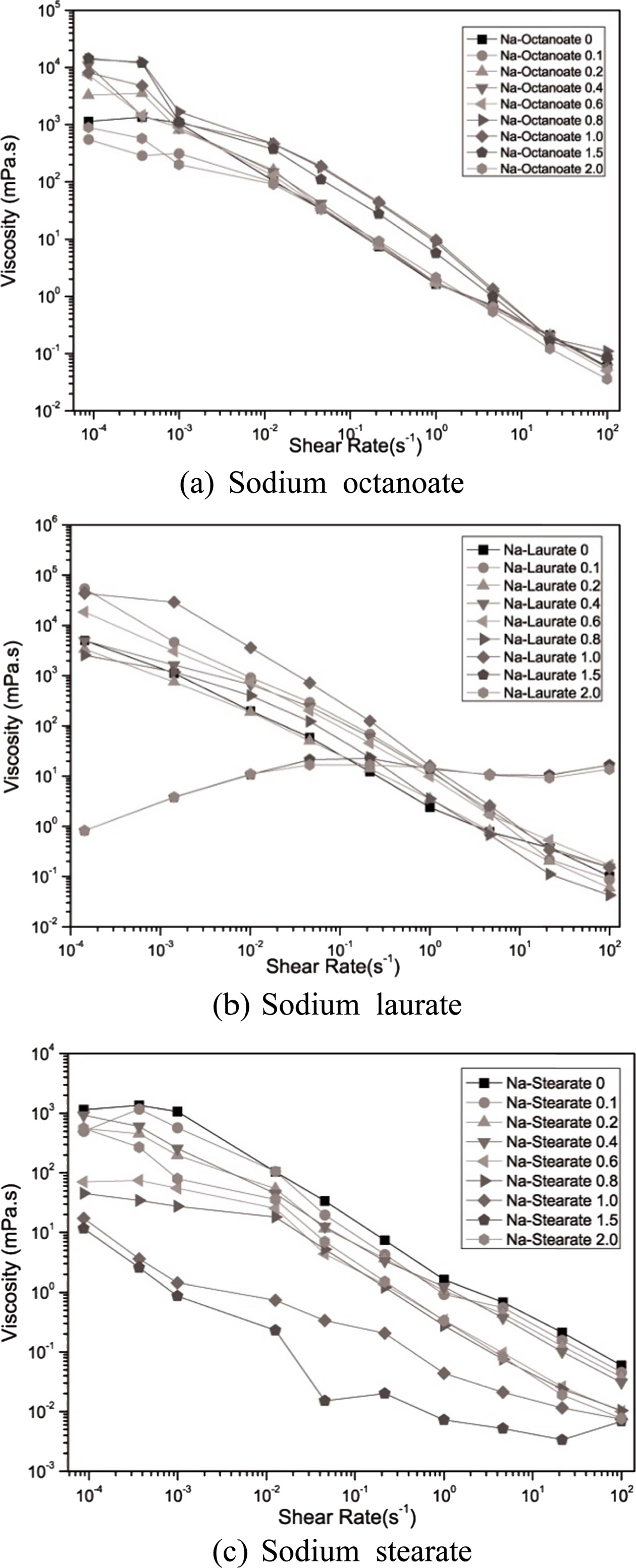
Except when Na laurate was added, an overall shear thinning behavior was noted, wherein the viscosity decreased when the shear rate increased. When Na-PAA and Na-PMAA were added, the viscosity decreased from 104 to 10-3 mPa·s as the shear rate increased. When Na laurate and Na octanoate, which are anionic surfactants, were added, the viscosity decreased from 104 to 10-1 mPa·s. This indicates that polyelectrolytes offer a higher dispersion efficiency than surfactants.
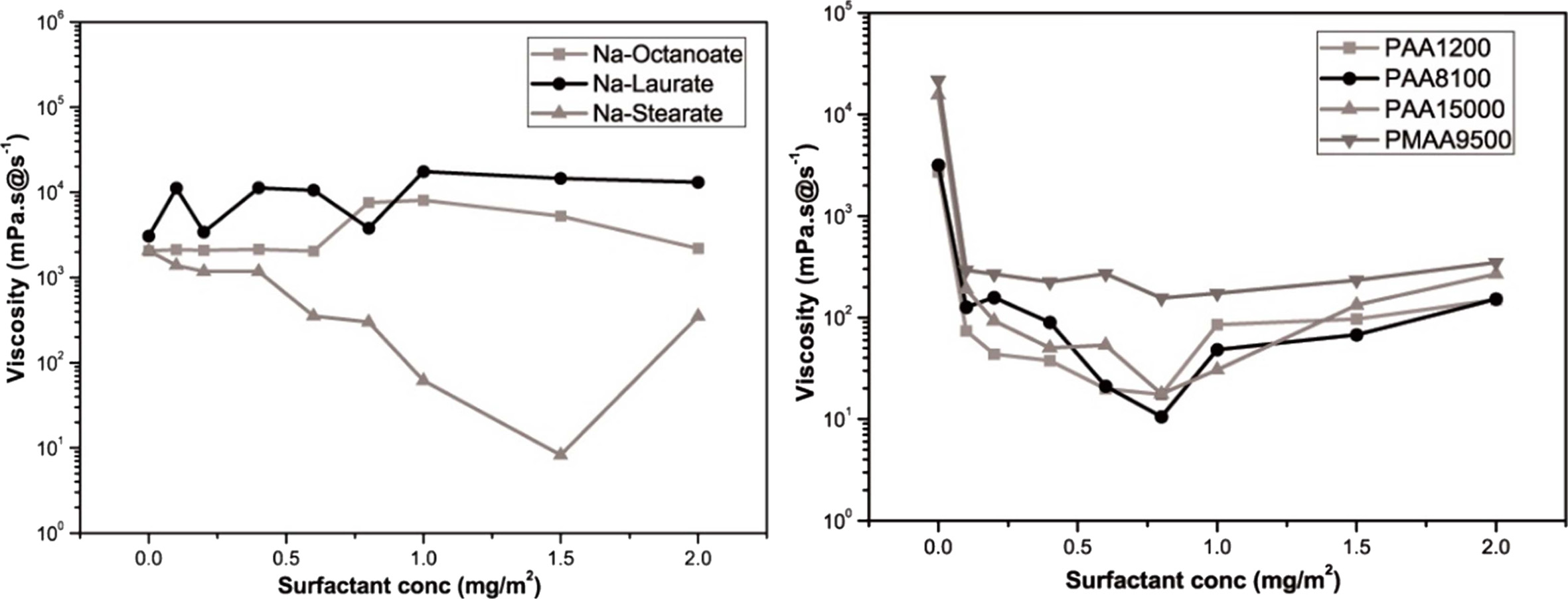
When the added amount of Na laurate ranged from 0 to 1.0 mg/m2, the viscosity decreased as the shear rate increased (Fig. 3). When the added amount was 1.5 mg/m2 or higher, the viscosity increased as the shear rate increased. Shear thickening was difficult to observe in the relatively dilute slurry, and its cause will be identified later through further research, as it was within the scope of this study. All the slurries with added Na octanoate and Na stearate exhibited shear thinning behavior. In particular, noticeable shear thinning was observed when the added amounts of Na stearate were 1.0 and 1.5 mg/m2. The shear thinning behavior is observed when the viscosity decreases as the aggregation between particles generated by van der Waals attraction is broken by shear stress [12].
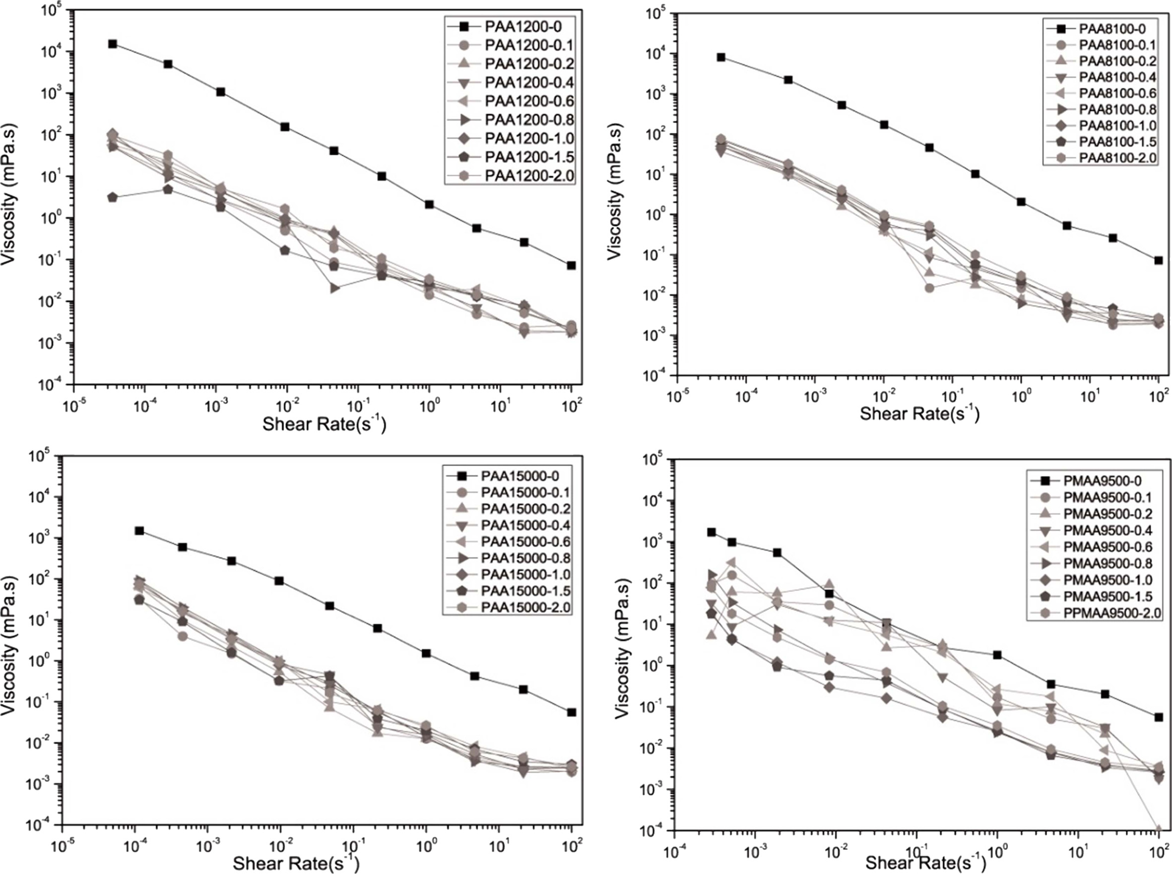
When examining the variation in the steady state flow of the prepared slurry according to the shear rate (Fig. 4) using anionic polyelectrolytes, similar shear thinning could be observed for all the samples. As the shear rate increased, the viscosity decreased from 104 to 10-2 mPa·s when Na-PMAA was added and from 104 to 10-3 mPa·s when Na-PAA was added.
The viscosity at the shear rate of 1/s was defined as the apparent viscosity using a steady-state flow graph. Using the result values obtained, the viscosity variation according to the amount of added dispersant is shown in Fig. 5. In the figure, the lowest viscosity can be observed at 1.5 mg/m2 of Na stearate as the anionic surfactant and at 0.8 mg/m2 of Na-PAA (M.w. = 8100 g/mol) as the anionic polyelectrolyte. For the inkjet printhead, a viscosity in the range of 8–25 mPa·s was required [13]. Although both the dispersants exhibited viscosity values in this range, Na-PAA (M.w. = 8100 g/mol) exhibited good dispersability for a smaller added amount. It was also considered that when too much surfactant is added, it could cause dissociation of Na+ ions and resultant flocculation of slurry [14].
The surface tension of the water-based ink needed to be adjusted to the range required by the printhead from the high initial value. As shown in Fig. 6, the surface tension decreased on the addition of the dispersant, as confirmed using two types of organosilicon polymers. Polydimethylsiloxane (BYK-310, BYK, Germany) was the most effective in this respect, as 1 wt% of it resulted in a surface tension of 23 mN/m, but it posed a problem of frit and layer separation over time. Polysiloxane (BYK-28, BYK, Germany) exhibited a slightly lower capability of decreasing the surface tension as 1 wt% of it led to a surface tension of 25 mN/m, but it did not lead to any compatibility issues. Therefore, polysiloxane was selected as the surface tension modifier: only 0.1 wt% of it was sufficient in reducing the surface tension to an appropriate value.
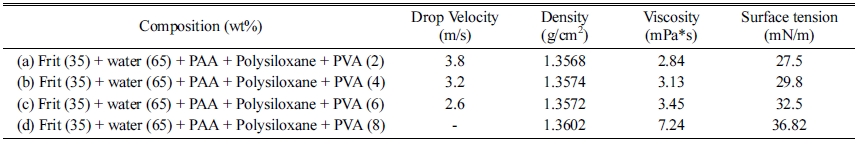
In general, the ink uses a rheology modifier to counter the sedimentation occurring during the storage [15]. To analyze the influence of the PVA on the glass frit ink, it (HS-BD25, San Nopco Korea, Korea) was added to the glass frit slurry to an optimal dispersibility and surface tension and the droplet formation behavior was examined. After fabricating the frit binder slurry by adding 0.8 mg/m2 of Na-PAA (Mw 8100 g/mol) and 1.0 wt% of polysiloxane, PVA was added at various contents of 2, 4, 6, and 8 wt%. Table 2 shows the compositions and physical characteristics of the frit binders with PVA.
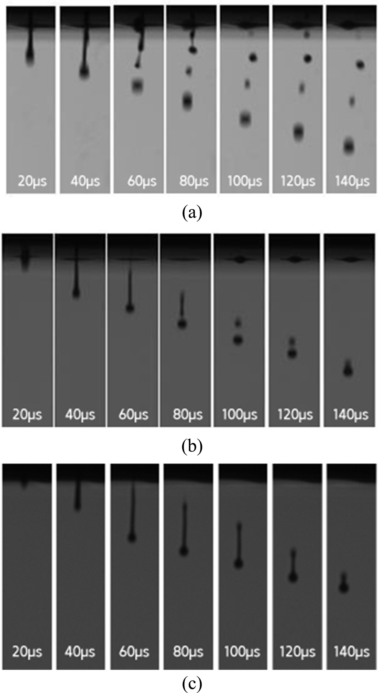
For the glass frit binder with 2 wt% PVA, the tails of the droplets separated and satellite droplets were formed in the ejection process. The satellite droplets were ejected in different directions from the main droplet at different speeds (Fig. 7). For the binder with 4 wt% PVA, the droplet tail separation phenomenon was observed at 100 μs, but the separation distance was not large and the separated droplet merged again with the main droplet at 140 μs. For the binder with 6 wt% PVA, no satellite droplet was observed and the formation of a single spherical droplet was confirmed at 140 μs. For the binder with 8 wt% PVA, ink ejection from the head was not possible. Table 3 shows the optimized composition of the glass frit binder.
3D Printing ceramics using the glass frit binder
Bar-shaped specimens were formed using the optimized glass frit binder. As the forming time increased, the number of service station entries for head cleaning increased. This appeared to be because the frit solids contained in the binder dried on the nozzle surface. Fig. 8 is a photograph of the nozzle after the service station entry of the 3D printer was forcibly suppressed and a specimen was formed using approximately 40 mL of the glass frit binder. As can be seen in the figure, frit solids clogged the nozzle. The continuously occurring frit binder drying issue could be somewhat suppressed by the increase in the flow rate of the ejected binder. To improve the drying problem occurring around the nozzle of the glass frit binder, the ejection amount of the binder was increased by approximately 120% from 0.507 mL/cm3 to 0.650 mL/cm3, and the number of the service station entry performing head cleaning was increased to five times from 0.1 to 0.5 per layer. The ejection amount of the binder was not increased further because damage to the layers was observed during the spread sequence of the powder when the amount exceeded 0.650 mL/cm3.
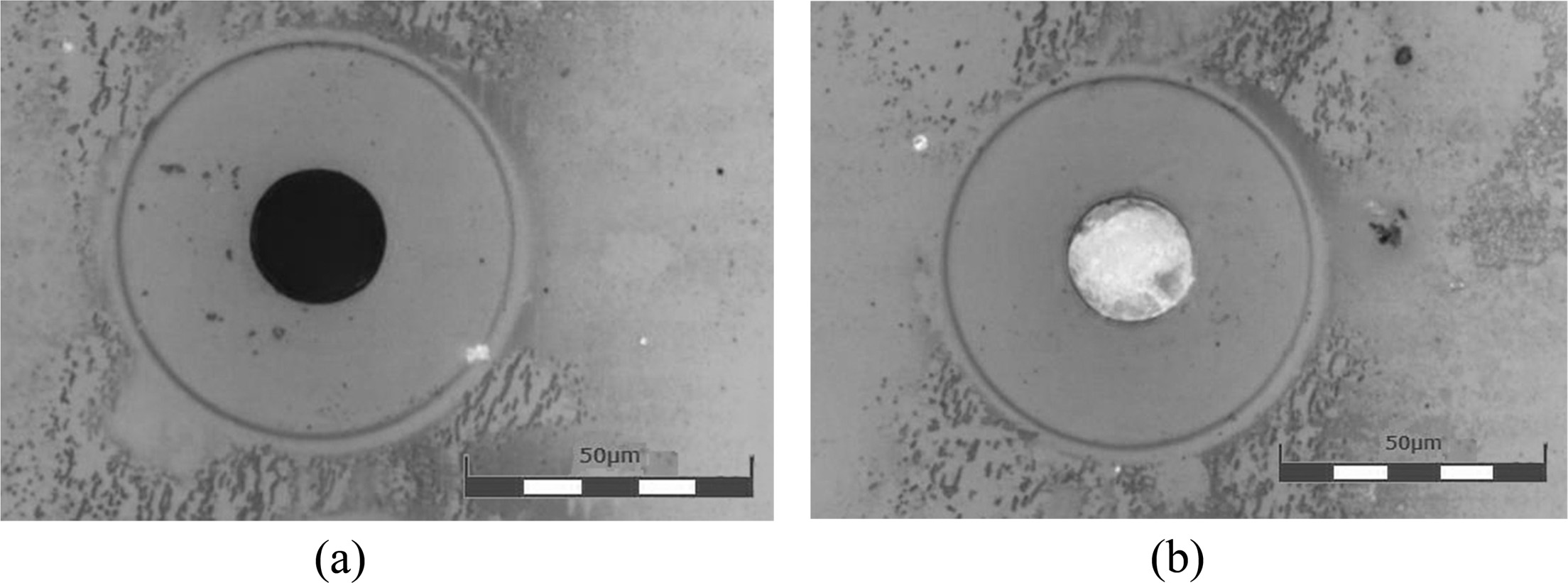
Clogging of the nozzle by frit solids did not occur during forming to such an extent that the function of the nozzle was restricted. This is because the binder was continuously ejected through the nozzle and service station entry was periodically performed for cleaning the head surface. However, once the head parking mode was entered after stopping the forming, the frit binder remaining in the nozzle exposed to the atmosphere began to dry and completely closed the nozzle after approximately ten minutes. To address this problem, it is necessary to improve the closed structure of the parking station and to add a step of forcibly purging the remaining binder. Fig. 9 shows the nozzle status at different time points. As can be seen in the figures, the nozzle was clearly visible immediately after parking but was blocked owing to drying of the frit binder after approximately ten minutes.
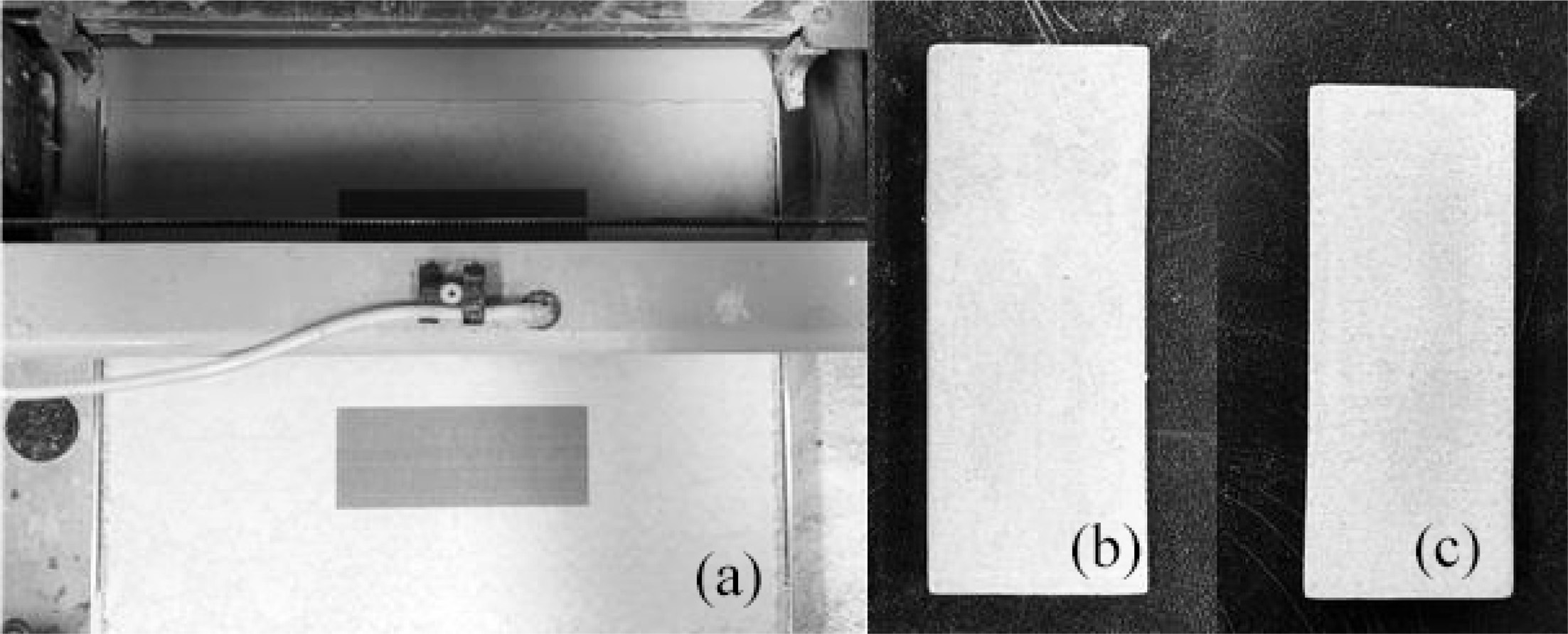
Fig. 10(a) shows the normal formation of ceramic specimens in the binder jetting 3D printer using the glass frit binder. Fig. 10(b) and (c) show the dried and sintered specimens, respectively. The formed body exhibited forming strength that could sufficiently withstand handling for the next process.
The formed specimens were sintered at 1,200 ℃, 1,250 ℃, and 1,300 ℃. Fig. 11 shows the densities and water absorption rates of the specimens for various firing temperatures. The density increased by approximately 19% for the specimen fabricated with the glass frit binder at all temperatures, and the water absorption rate decreased by approximately 17–22%. This was attributed to the glass frit contained in the binder melting in the sintering process and filling the pores, which contributed to densification in the liquid phase sintering. At 1,300 ℃, the highest densities were observed for both the binder specimens, but severe sintering deformation of the specimens was also observed. This was attributed to the specimens being subjected to over-firing due to the temperatures being higher than the recommended sintering temperature for ceramic powders, as determined in a previous study.
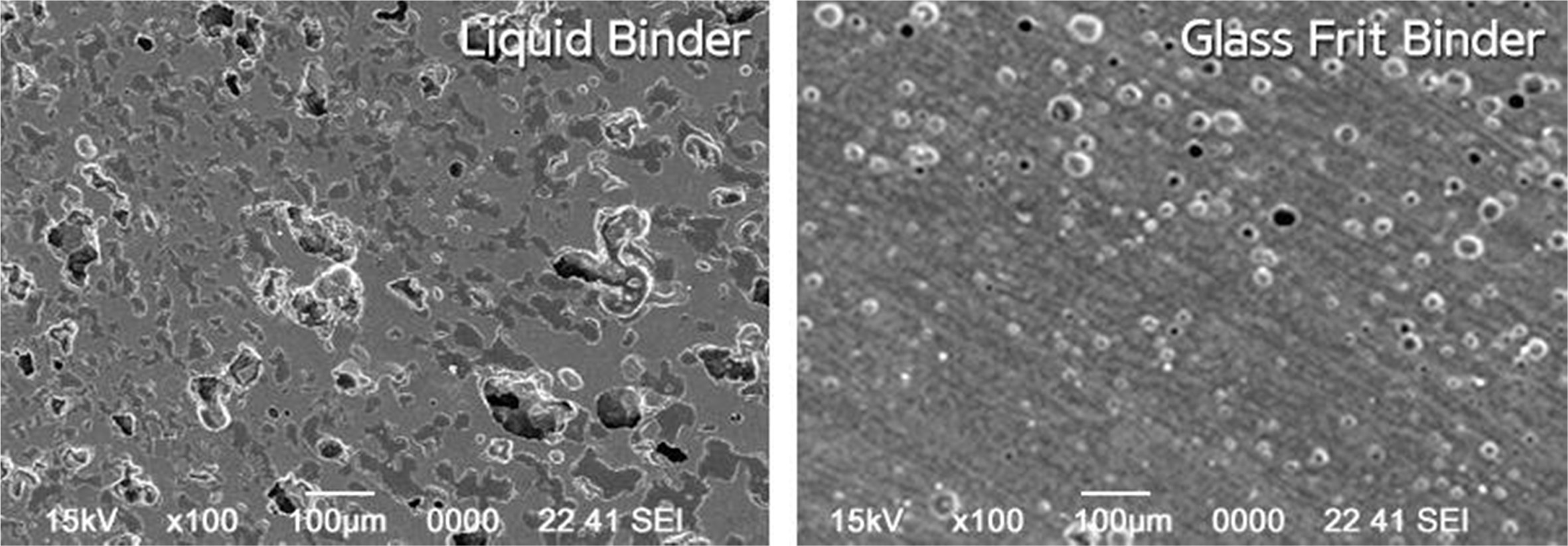
Fig. 12 shows the microstructures of the sintered specimen. As can be seen in the figures, the pore shape was close to a sphere and the pore ratio was relatively low for the specimen with the glass frit binder. This could be because the glass frit contained in the binder affected the sintering process and resulted in microstructures on further sintering.
|
Fig. 3 Fluidity change noted in the slurry due to the addition of anionic surfactants. |
|
Fig. 4 Variation in the viscosity with the shear rate for different amounts of polymer dispersant added. |
|
Fig. 5 Viscosity of the frit binder ink for various dispersant addition amounts. |

|
Fig. 6 Dependence of the surface tension of the frit binder ink on the additive content. |
|
Fig. 7 Droplet ejection behavior of the frit binder ink on addition of (a) 2 wt%, (b) 4 wt%, and (c) 6 wt% of PVA. |
|
Fig. 8 Frit solids observed around the nozzle after forming. |
|
Fig. 9 Nozzle clogging (a) before parking and (b) 10 min after parking. |
|
Fig. 10 (a) 3D printing process using the glass frit binder, (b) dried specimen after forming, and (c) specimen sintered at 1,250 ℃. |

|
Fig. 11 Sintering densities and water absorption rates of specimens with different binders at various firing temperatures. |
|
Fig. 12 Microstructures of the specimens sintered at 1,250 ℃ with different binders. |
A glass frit binder was used to improve the density of a binder jetting 3D-printed specimen. The viscosity, surface tension, and slurry stability were considered the key factors determining the ejection behavior of the ink used in a binder jetting 3D printer. The optimal contents of additives were investigated and used for further investigations.
For the dispersion of frit particles in an aqueous system, the steady-state flow was analyzed against the shear rate using an anionic surfactant and an anionic polyelectrolyte, and then the apparent viscosity was obtained at a shear rate of 1/s. The optimal dispersant concentration was determined as 1.5 mg/m2 of Na stearate and as 0.8 mg/m2 of Na-PAA (Mw 8,100 g/mol). The addition of polysiloxane exhibited a surface tension of 25 mN/m and did not exhibit any compatibility problem. To stabilize the slurry, PVA was added and changes in the droplet formation behavior were observed. For the binder with 6 wt% PVA, no satellite droplet was observed and the formation of a single spherical droplet was confirmed at 140 μs.
It was possible to form ceramic specimens using the glass frit binder, and the formed body exhibited strength that could sufficiently withstand handling for the next process. After heat treatment at 1,200 ℃, the density of the specimen that used the liquid binder was 1.99 g/cm2 and that using the glass frit binder was 2.36 g/cm2. Similar increases were also observed at 1,250 ℃ and 1,300 ℃. The density increased by approximately 19% compared to that of the specimen fabricated with the liquid binder, and the water absorption rate was found to have decreased by 17–22%.
During printing process frit solids contained in the binder closed the nozzle of the head. This was due to the drying that began from the head surface exposed to the atmosphere after the completion of forming. The effect of the drying was not significant during forming, and it could be overcome satisfactorily by forcible purging of the remaining binder.
This work was supported by the Technology Innovation Program (10070165, Convergence of Traditional Ceramicware Process and Digital 3D Printing Process for High-Value-Added Bone China Porcelain) funded by the Ministry of Trade, Industry & Energy (MOTIE, Korea).
- 1. J.H. Choi, E.T. Kang, J.W. Lee, U.S. KIm, and W.S. Cho, J. Ceram. Process Res. 19[1] (2018) 43-49.
- 2. S. Maleksaeedi, H. Eng, F.E. Wiria, T.M.H. Ha, and Z. He, J. Mater. Process. Tech. 214[7] (2014) 1301-1306.
-

- 3. B. Derby and N. Reis, MRS Bulletin 28[11] (2003) 815-818.
-
- 4. A. Lee, K. Sudau, K. Ahn, S. Lee, and N. Willenbacher, Ind. Eng. Chem. Res. 51[40] (2012) 13195-13204.
-
- 5. D.W. Jang, D.J. Kim, and J.H. Moon, Langmuir 25[5] (2009) 2629-2635.
-
- 6. J. Cesarano, I. A. Aksay, and A. Bleier, J. Am. Ceram. Soc. 71[4] (1988) 250-255.
-
- 7. S. Wee, S. Oh, J. Lee, Y. Lee, and J. Chung, Trans. of Korean Soc. Mecha. Eng. B 30[10] (2006) 1003-1011.
- 8. E. Özkol, J. Ebert, and R. Telle, J. Eur. Ceram. Soc. 30[7] (2010) 1669-1678.
-
- 9. M. Dondi, M. Blosi, D. Gardini, and C. Zanelli, Ceram. Forum. Inter. 89[1] (2012) 1-11.
- 10. Fujifilm Dimatix Inc, Jettable Fluid Formulation Guidelines (2013) p. 1.
- 11. G. Ewers, XAAR Application Note [4] (2015) 1-11.
- 12. M. Itoh, O. Sakura, M. Hashiba, K. Hiramatsu, and Y. Nurishi, J. Mater. Sci. 31[12] (1996) 3321-3324.
-
- 13. I. Hutchings, Qualicer 2010-XI Global Forum on Ceramic Tile, (2010) 1-17.
- 14. J. Chang, F. Lange, and D. Pearson, J. Am. Ceram. Soc. 77[1] (1994) 19-26.
-
- 15. D. J. Shanefield, in “Organic Additives and Ceramic Processing with Applications in Powder Metallurgy Ink and Paint” (Springer 1995) p. 32.
 This Article
-
2019; 20(5): 547-555
Published on Oct 31, 2019
- 10.36410/jcpr.2019.20.5.547
- Received on Apr 17, 2019
- Revised on Jun 12, 2019
- Accepted on Jul 10, 2019
Services
- Abstract
introduction
experimental
results and discussion
conclusions
- Acknowledgements
- References
- Full Text PDF
Shared
Correspondence to
- Woo-Seok Cho
-
Korea Institute of Ceramic Engineering and Technology, 3321 Gyeongchung-daero, Sindun-myeon, Icheon-si, Gyeonggi-do, Korea
Tel : +82-31-645-1439
Fax: +82-31-645-1440 - E-mail: wscho@kicet.re.kr
Clean-Energy Research Institute(CRI), Hanyang University, 222, Wangsimni-ro, Seongdong-gu, Seoul, 04763, Korea
E-mail: jcpr@hanyang.ac.kr