


- Synthesis of carbon nanotubes on template coated biomorphic composites
Jung Gyu Parka, Se Young Kimb, In Sub Hanb, Hyun Sung Kimc and Ik Jin Kima,*
aInstitute for Processing and Application of Inorganic Materials, (PAIM), Department of Materials Science and Engineering, Hanseo University, 46, Hanseo 1-ro, Haemi-myun, Seosan-si, Chungnam 31962, Korea
bKorea Institute of Energy Research (KIER), 152, Gajeong-gu, Daejeon 34129, Korea
cDepartment of Chemistry, Pukyong National Universiy, 45, Yongso-ro, Nam-gu, Busan 48513, Korea
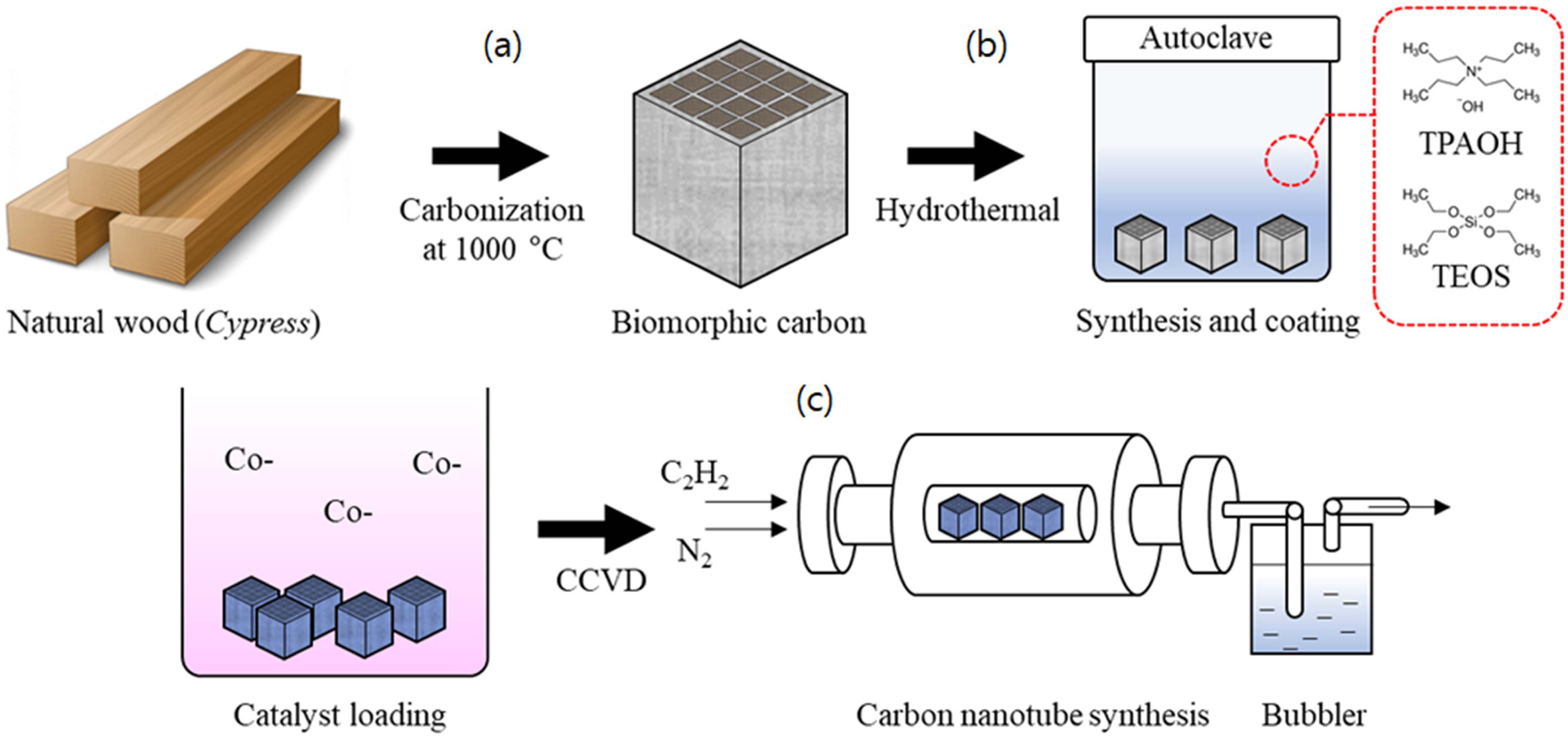
The novel processing route for the synthesis of carbon nanotubes (CNTs) on silicalite-1 template coated biomorphic carbon is reported in this paper. First of all, biomorphic carbon with 20-35μm pore dimension was prepared by carbonizing Cypress under Ar atmosphere, thereafter, a silicalite-1 crystals were synthesized and homogeneously coated on biomorphic carbon by an in situ hydrothermal process. Finally, multi-walled carbon nanotubes synthesized on the Co-metal nanoparticles loaded silicalite-1 template loaded on biomorphic carbon with acetylene (C2H2) as a carbon source by the catalytic chemical vapor deposition (CCVD) method. In this study, we focused on varying the reaction time for obtaining better CNTs yield and the characterization morphology, crystallinity, surface area of CNTs were investigated. Multi-walled CNTs with inner diameter of 7.31nm and outer diameter 38.53 nm and the maximum yield of 23.71% nm were synthesized at 650°C for180 min and the ID/IG of 0.97-1.00 of CNTs was obtained.
Keywords: Biomorphic carbon, Silicalite-1, Composite, Catalytic Chemical vapor deposition, Carbon nanotubes
Biomorphic carbon is a newly investigated material for synthesizing carbon nanotubes (CNTs) with novel hierarchical and complex microstructures using natural biological materials, such as wood [1], rattan [2], and rice husk [3]. Amongst these, wood has been paid considerable attention with respect to the conversion of its tissue to ceramic materials because it has highly anisotropic cellular structures [4]. Wood has been used to fabricate various carbon composites for the synthesis of CNTs and are of different types and are classified into the following two groups according to the density or porosity of the products.
As might be expected, natural evolution through the ages has provided biological bulk materials with unique and sophisticated structures from renewable resources such as wood. Through pyrolysis of natural wood, a carbonaceous perform can be produced with fine hierarchical porous structure, ranging from millimeter via micrometer through to nanometer scale [5, 6]. At the same time, the resource of wood is abundant and different species of wood exhibits a large variety of available pore structure for the applications including filters, catalyst support, and porous ceramics [7]. Economically, the use of wood provides a low cost starting material that has near-net and complex shape capabilities, instead of the simple shapes that are normally produced by material processing techniques [8-10].
Silicalite-1, isostructural silica with an MFI structure has a three-dimensional combination of interconnected 10-membered-ring straight (pore diameter: 5.1 × 5.6 Å) and zigzag pore diameter: 5.7 × 4.6 Å) channel systems. Due to its unique channel structure, silicalite-1 is one of the industrial important zeolites that, in addition to conventional applications such as many aromatic and non-aromatic hydrocarbon adsorption [11], catalysis [12], separation [13] and advanced photonic applications [14] based on thin films and membranes. In the present review, we discuss the methods available for introducing mesopores into silicalite-1 to create hierarchical materials with improved performance. Most importantly, the different methods and materials are categorized to clearly illustrate the recent progress in this field and to point to new challenges and opportunities [15, 16].
In this study, the formation of CNTs in a silicalite-1 template coated biomorphic carbon using the catalytic chemical vapor deposition (Cat-CVD) method is reported. The synthesis was carried out with the application of the three-step processing route for CNT composites. First, a biomorphic carbon was produced by a carbonizing reaction. Secondly, the silicalite-1 were synthesized within and coated simultaneously on the biomorphic carbon using the in situ method. The biomorphic carbon was then subjected to a wetting process that resulted in the formation of a Co-ion-loaded silicalite-1 template, and finally, the CNTs were synthesized using the Cat-CVD method. The effects of the reaction temperature and time on the morphology, yield, and surface area of the CNTs were investigated, thereby requiring the performances of high-resolution transmission electron microscopy (HRTEM), field emission scanning electron microscope (FESEM), thermo-gravimetric-analysis (TGA), Raman-spectra, and Brunauer-Emmett-Teller (BET) analysis of the microstructural properties of the synthesized-CNT carbon matrix.
Raw Materials
For biomorphic carbon, sapwood of Cypress (Chamaecyparis obtuse) was used. To prepare silicalite-1 crystal, tetrapropylammonium hydroxide solution (TPAOH, 1.0 M in H2O, Sigma-Aldrich) as template, tetraethyl orthosilicate (TEOS, 98%, Sigma-Aldrich) as precursor. To dissolve TPAOH distilled water also used Co chloride hexahydrate (CoCl2·6H2O ≥ 99.0%), purchased from Samchun Pure Chemical (South Korea), was used as the catalyst, and C2H2 from Kyuongin Chemical Industry (South Korea) was used as the carbon source. Further, nitrogen gas (N2, 99.99 %) from Doekyang Co. Ltd. (South Korea), deionized water, and ethanol (EtOH, 94.5%) from Samchun Pure Chemical (South Korea) were the other chemicals that were used.
Preparation of the biomorphic carbon
Biomorphic carbon was prepared using the following steps. Primarily, Cypress columnar samples with a square cross-section and dimensions of 10 × 10 × 20 mm3 were prepared. The samples were then dried in an oven chamber at 120 ℃ for 24 hr. Secondary, to maintain neutrallity, the biomorphic carbon was prepared by the pyrolysis of the spruce specimens in the presence of inert gas. To avoid the collapse of the sample during the carbonizing process, the samples were gently heated up to 600 ℃ with a heating rate of 0.5 ℃/min for 6-8 hr in a horizontal electric furnace with an N2 flow (10 sccm). Finally, the temperature was raised up to 1000 ℃ at the rate of 3 ℃/min under a vacuum atmosphere, and this was followed by an air-cooling to room temperature to accrue the porous biomorphic carbon, as shown in Fig. 1(a). The biomorphic carbon thus prepared was found to have pore size of 16.02 um porosity of 82.16% followed by comparative strength of 52.65 Mpa with the wall thickness of 2.31 um. The XRD pattern has the peaks at 2 theta values, 23° and 45° which are attributed to sp2 carbon correspond to (002) and (10l) plane, respectivley.
Synthesis and coating of silicalite
Synthesis of silicalite-1 was obtained by a hydrothermal reaction which used for mother solution TPAOH : TEOS : H2O of a molar ratio of 1.5 : 7 : 360. The initial solution is prepared by adding 7.6 g of TPAOH and 162 g of H2O in a 500 mL HDPE bottle and magnetic stirring for 1.5 hours. After that, the reaction solution was made by adding 36.4 g of TEOS drop wise slowly to the initial solution under high-speed stirring. After sealing the reaction solution in an HDPE bottle, stir for 2 hours and transfer to a Teflon-lined stainless-steel pressure vessel (also known as an autoclave). Biomorphic carbon was dipped into a reaction solution and allowed to age for 12 hours at room temperature. Finally, a fully sealed autoclave is placed in an oven and hydrothermally synthesized at 150 ℃ for 12 hours is shown in Fig. 1(b).
Synthesis of CNTs
Fig. 1(c) shows the schematic diagram to show the novel process of the synthesis of CNTs in a silicalite-1 template is loaded to biomorphic carbon. Preperation of biomorphic carbon is explained in above paragraph. After the carbonization of wood and the coating of silicalite-1 crystal on biomorphic carbon, the catalytic decomposition of carbon source (acetylene) on the silicalite-1 coated biomorphic carbon was carried out in a quartz tube centered in an electric tube furnace. The temperature wasraised a rate of 5 ℃/min to the desired reaction temperature in a nitrogen atmosphere (200 sccm) to maintain neutrality. Carbon nanotubes were grown(c) by the CCVD method by the introduction of carbon feeding gas C2H2 (10 sccm).
|
Fig. 1 Schematic diagram of the novel processing of synthesis CNTs on biomorphic carbon: Carbonization process (a), silicalite-1 coating process (b), and CNTs synthesis (c). |
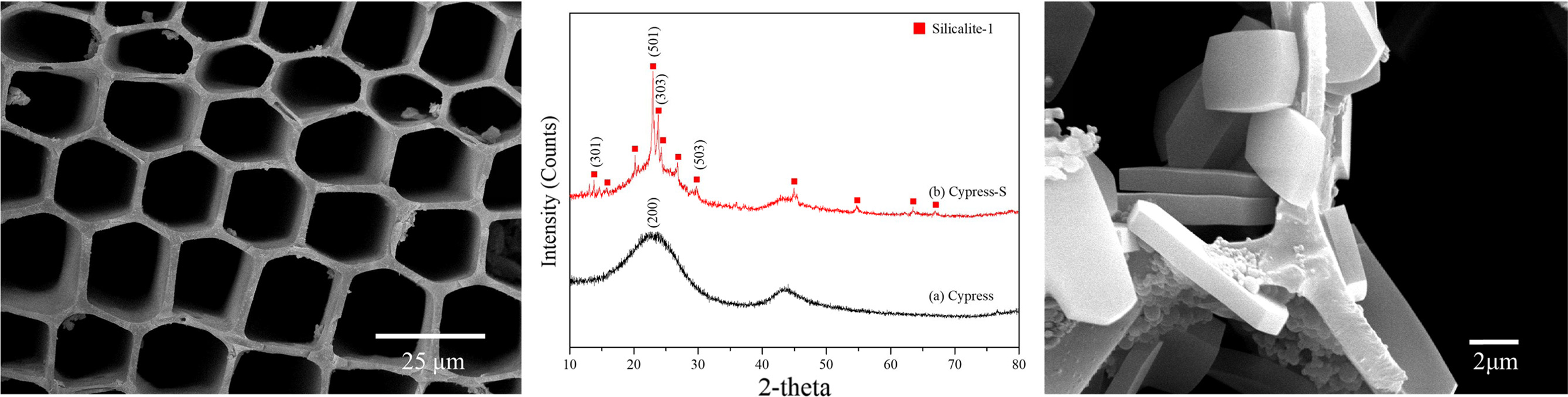
FESEM images of the cross section and XRD patterns of biomorphic carbon and silicalite-1 template coated materials are shown in Fig. 2(a) and (b), respectively. The sophisticated materials showed a microcellular foam like honeycomb structure with a high porosity of 82.16%, an average cell size in the range of 16.02, and an average wall thickness of 2.31 um. The compressive strength of the sample was 52.65 MPa. The XRD patterns of carbonized basic biomorphic materials showed the typical graphite structure with major broad peaks located at 25º(002) and a lower intensity at 45º(10l). This is suggestive of the development of hexagonal network layers stacked roughly parallel to each other, i.e. turbostratic structure, which indicates the regularity of carbon in biomorphic carbon materials is poor [17]. XRD pattern of silicalite-1 crystal synthesized and coated sample showed the pure silicalite-1 with orthorhombic, Pnma space group, the unit cell of a = 2.00801(2) nm, b = 1.99239(2) nm, and c = 1.34167(1) nm, and located the major peaks at 13° (301), 24° (501) and 25° (303), respectively [18].
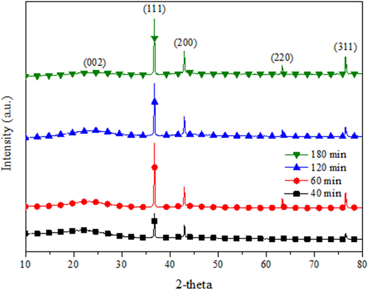
Fig. 3 shows XRD patterns of CNTs synthesized on silicalite-1 coated biomorphic carbon as function of reaction time. The lower (002) intensity is traditionally used to estimate a graphitization degree of carbon. In general, growing disorder in the materials is also reflected in increased values of d(002) [19]. As shown in Fig. 3, the (111) and (200) intensity increases with increasing reaction time, which means the structure of CNTs-biomorphic carbon materials evolved toward that of a good crystallized silicalite-1.
Fig. 4 shows FESEM images of CNTs that are grown on silicalite-1 coated biomorphic carbon by the CCVD method. Each image represents CNTs synthesized at 60 min. and 120 min. correspondingly in Fig. 4(a), (b) respectively. All the images clearly show CNTs synthesized inside and around pores. In particular, CNTs grew intensively over the cell wall. Fig. 4(a) shows that the CNTs grown at 650 ℃ for 60 min are comparatively thin, and not as fully synthesized as those grown for 120 min. On increasing the reaction time, the synthesized CNTs founded to be more entangled and close networks overall silicalite-1 coated biomorphic carbon as shown in Fig. 4(b). According to the FESEM image results, CNTs synthesized at a growth temperature of 650 ℃ for 120 min are sufficiently fully grown structure of CNTs.
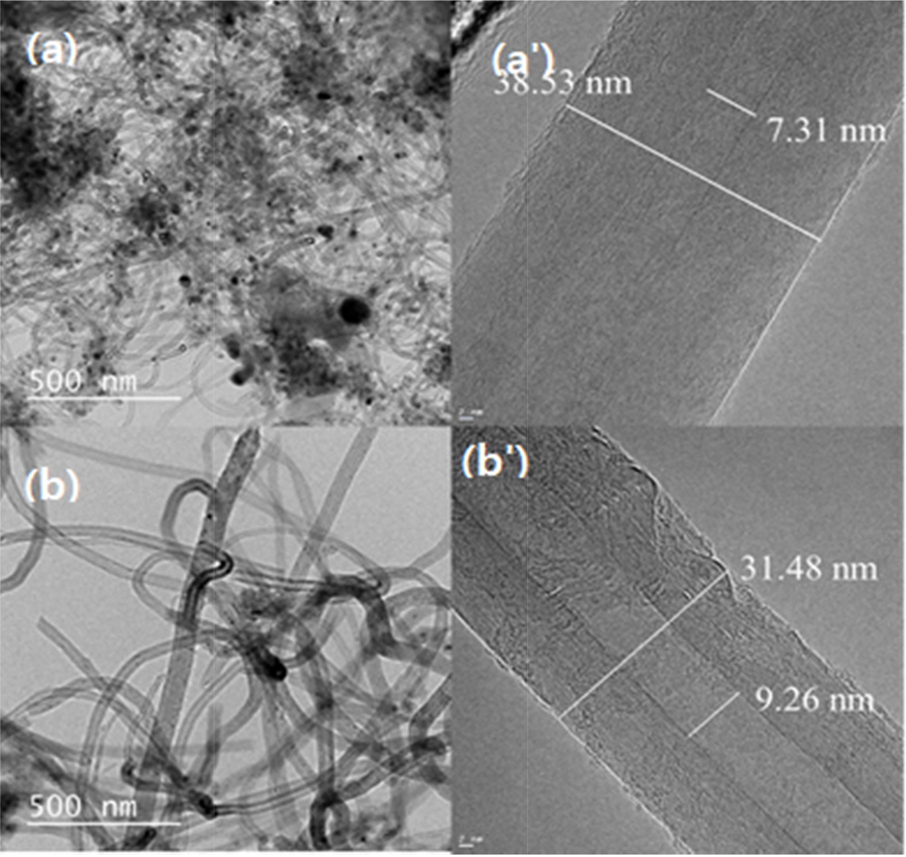
Fig. 5 shows the HRTEM images of multi-walled CNTs grown min at 650 ℃ for (a) 60 min and (b) 120 min respectively. The synthesized CNTs is shown in Fig. 5(a') have a comparatively thicker outer wall, which forms a densely-layered structure with an outer diameter of around 38.53 nm with inner diameter of 7.31 nm. A base growth mechanism can be clearly seen in the CNTs, which are known for having better attachment tendencies to the substrate. The CNTs in the TEM images of Fig. 5(b') show also thicker outer walls, with a diameter of around 31.48 nm. with an inner diameter of 9.26 nm Also, note here the apparent growth in terms of the inner and outer diameter of the nanotubes. Hence, it can be inferred that the decomposition of carbon atoms from C2H2, which forms coaxial cylindrical graphene sheets layer by layer around the CNT core, strongly relates to the reaction time and temperature. All the CNTs samples display bamboo-like structure and are typically multi-walled CNTs (MWCNTs). Moreover, it can be clearly it can be inferred from the HRTEM images below that the CNTs grown for 120 min have better yield with smooth outer and inner wall in comparison to the one synthesized for 60 min.
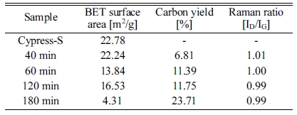
Fig. 6 shows the N2 adsorption/desorption isotherms of Co loaded silicalite-1 loaded biomorphic carbon and CNTs grown at 650℃ for 40 min, 60 min, 120 min and 180 min, respectively. As illustrated in Fig. 8, the adsorption and desorption isotherms of N2 for the Co loaded silicalite on biomorphic carbon and CNTs grown at 650 ℃ for (b) 40 min, (c) 60 min, (d) 120 min and (e) 180 min are clearly of type IV, according to the IUPAC classification of adsorption isotherms. Type IV isotherms characteristically show the simultaneous presence of micro- and mesopores. it is obvious that the adsorption capacities of CNTs were all increased with the increased in reaction time [20]. And all of the samples possess relatively high adsorption performance. Compared with Co loaded silicalited-1 biomorphic carbon, the adsorption capacity of CNTs silicalite-1 supported biomorphic carbon is markedly lower. For CNTs Co loaded silicalite-1 biomorphic carbon, silicalite-1 biomorphic carbon is the skeleton and is coated on it, and then silicalite-1 supported biomorphic carbon would be the mainly adsorbent. And the physical properties of the Co loaded silicalite-1 biomorphic carbon and CNTs grown at 650 ℃ for 40 min, 60 min, 120 min and 180 min, such as surface areas, reaction temperature, carbon yeild, raman ratio and BET surface area are summarized in Table 1.
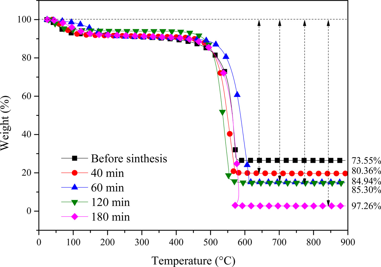
Fig. 7 shows the TGA curves of the CNTs grown for 40, 60, 120 and 180 min at 650 respectively. All CNTs samples represent an initial weight loss tendency, which may occur through the loss of physically adsorbed water by the silicalite-1 until 195 ℃. In the subsequent heating process, both and samples undergo a two-step weight loss pattern up to 97%. In the first step (458 ~ 633℃ and 485 ~ 717 ℃, respectively), the amorphous carbon has been combusted, and in the second step (≥ 633 ℃ and ≥ 717 ℃, respectively), the MWCNTs have combusted until 800 ℃. After that, the samples maintain a weight loss pattern due to biomorphic carbon combustion. The main reason for the two-step pattern is that the decomposition of C2H2 on metal catalysts leads to the formation of CNTs as amorphous carbon [15, 21]. The carbon yield from CNTs synthesized by metal-containing CCVD is calculated as follows:
Carbon yield (%) = (mtot – mcat) / mcat × 100%
where, mcat is the initial catalyst amount (before reaction), and mtot is the total sample weight after synthesis [22]. The TGA curves allow estimate of the amount of carbon yield.
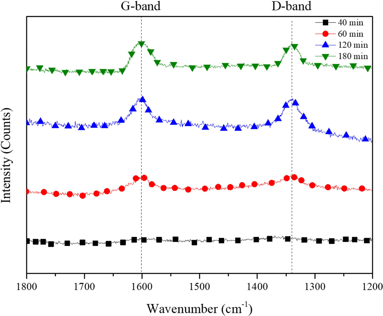
The Raman spectra for the CNTs synthesized for 40, 60, 120 and 180 min are presented in Fig. 8. All the four spectra are dominated by two strong peaks around 1340 and 1620 cm-1. The accepted nomenclature for these two peaks are D and G bands, respectively. They are characteristic for disordered sp2-hybridised carbon materials and have been observed in all reported Raman spectra of MWCNTs. The D-band is formed by the defects in the graphite crystals and by finite sizes of graphite crystallites in the material. Moreover, pyrolitic carbon particles deposited on the nanotubes also contribute to the rise of D-band. The G-band corresponds to the tangential stretching (E2g) mode of highly oriented pyrolitic graphite (HOPG) and indicates the presence of crystalline graphitic carbons in the MWCNTs. The strength of the D-band relative to the G-band is a measure of the amount of disorder in the CNTs and is used for qualitative characterizations of the nanotubes [23]. The relative intensities of the D- to G-bands (ID/IG ratio), as revealed by the Raman spectroscopy, which is a measure of the degree of graphitization, were also provided in Table 1. The carbon yield of 6.81 to 23.71 followed by BET of BET ranging from 4.31 to 22.24 was achieved with the reaction time of from 40 to 180 minute followed by ID/IG values from this work are between 0.99 and 1.01 which is in accordance with that reported in the literature (ID/IG = 0.97-1.00) for CVD-grown MWNTs.
|
Fig. 2 FESEM image and XRD patterns of silicalite-1 template coated biomorphic carbon. |
|
Fig. 3 XRD patterns of CNTs -biomorphic carbon as function of reaction time at 650 ℃. |

|
Fig. 4 FESEM image of CNTs synthesized on silicalite-1 coated biomorphic carbon at 650 ℃ for (a) 60 min and (b) 120 min. |
|
Fig. 5 HRTEM image of CNTs synthesized on silicalite-1 coated biomorphic carbon at 650 ℃ for (a) 60 min and (b) 120 min. |

|
Fig. 6 BET surface area of CNTs synthesized on silicalite-1 coated biomorphic carbon |
|
Fig. 7 TGA curves of the CNTs grown for 40, 60, 120 and 180 min at 650 respectively. |
|
Fig. 8 Raman spectra of CNTs synthesized on silicalite-1 coated biomorphic carbon. |
|
Table 1 Quality of CNTs (Raman spectra) and the Carbon Yield (TGA) with respect to the Reaction Temperature |
Silicalite-1 template coated biomorphic carbon having a large amount of MWCNTs were synthesized by a novel processing route that unified three independent processing techniques in succession. Owing to the high porosity of both the biomorphic carbon and the silicalite-1 template, the C2H2 supply to the catalytic metal nanoparticles was very easy, leading to the growth of uniform and dense CNTs across the entire biomorphic carbon. Reaction time of 650 ℃ was chosen as the optimum temperature for the maximum yield of CNTs of about 23.71% with inner diameter of 9.26nm and outer diameter of 31.48 nm was achieved. The results show the difference in morphology, yield content, and crystallinity with in various reaction. The ID/IG ratio from this analysis was found between 0.99 and 1.01, which is in accordance with those reported in the literature (ID/IG = 0.7-1.3) for CVD-grown MWNTs.
This research was supported by Basic Science Research Program through the National Research Foundation of Korea (NRF) funded by the Ministry of Education (NRF-2018R1D1A1B07049071).
- 1. C.R. Rambo, J. Cao, O. Rusina, and H. Sieber, Carbon 43 (2005) 1174-1183.
-

- 2. A. Zampieri, S. Kullmann, T. Selvam, J. Bauer, W. Schwieger, H. Sieber, T. Fey, and P. Greil, Micropor. Mesopor. Mater. 90[1-3] (2006) 162-174.
-
- 3. V. Martı´nez, M.F. Valencia, J. Cruz, J.M. Mejía, and F. Chejne, Ceram. Int. 32[8] (2006) 891-897.
-
- 4. C. Zollfrank, R. Kladny, and H. Sieber, J. Eur. Ceram. Soc. 24 (2004) 479-487.
-
- 5. A. Bachtold, P. Hadley, T. Nakanishi, and C. Dekker, Science 294 (2001) 1317-1320.
-
- 6. W.I. Milne, K.B.K. Teo, and G.A.J. Amaratunga, J. Mater. Chem. 14 (2004) 933-943.
-
- 7. K. Hata, D.N. Futaba, K. Mizuno, T. Namal, M. Yumura, and S. Iijima, Science 306 (2004) 1362-1364.
-
- 8. A. Thess, R. Lee, P. Nikolaev, H. Dai, P. Petit, J. Robert, C. Xu, Y.H. Lee, S.G. Kim, A.G. Rinzler, D.T. Colbert, G.E. Scuseria, D. Tomanek, J.E. Fischer, and R.E. Smally, Science 273 (1996) 483-487.
-
- 9. M. Zhou, D. Zang, X. Zhai, Z. Gao, W. Zhang, and C. Wang, Ceram. Intl. 42 (2016) 10704-10710.
-
- 10. Reactive processing of environmentally conscious biomorphic ceramics from natural wood precursors, Jour. Eur. Ceram. Soc. 24 (2016) 209-217.
-
- 11. C.D. Baertsch, H.H. Funke, J.L. Falconer, and R.D. Noble, J. Phys. Chem. 100[18] (1996), 7676-7679.
-
- 12. S. Barot, M. Nawab, and R. Bandyopadhyay, Journal of Porous Materials 23[5] (2016), 1197-1205.
-
- 13. E. Mateo, R. Lahoz, G.F. de la Fuente, A. Paniagua, J. Coronas, and J. Santamaría, Chem. Mater. 19[3] (2007), 594-599.
-
- 14. K. Lazarova, H. Awala, S. Thomas, M. Vasileva, S. Mintova and T. Babeva, Sensors,14[7] (2014) 12207-12218.
-
- 15. W. Zhao, M.J. Lee, H.T. Kim, and I.J. Kim, Electron. Mater. Lett. 7 (2011) 139-144.
-
- 16. P. Gao, Y. Bai, S. Lin, W. Guo, and H. Xiao, Ceram. Intl. 34 (2008) 1975-1981.
-
- 17. A. Onodera, K. Terashima, and T. Urushihara, J Mater Sci 32(1997) 4309-4318.
-
- 18. M. Rieder, M. Klementová, L. Brabec, and M. Koĉiík, Stud. Surf. Sci. Catal. 158 (2005) 741.
-
- 19. A. Cuesta, P. Dhamelincourt, J. Laureyns, J Mater Chem 8[12] (1998) 2875-2879.
-
- 20. A. Aliyu, A.S. Abdulkareem, A.S. Kovo, O.K. Abubakre, J.O. Tijani, and I. Kariim, Carbon Letters 21 (2017) 33-50.
-
- 21. W. Zhao, H.T. Kim, and I.J. Kim, J. Ceram. Process. Res. 13 (2012) 81-85.
- 22. J.G. Park, B. Basnet, S.Y. Kim, I.S. Han, and I.J. Kim, J. Ceram. Proc. Res. 19 (2018) 311-315.
- 23. M. Zdrojek, W. Gebicki, C. Jastrzebski, T. Melin, and A. Huczko, Solid State Phenomena 99-100 (2004) 265-268.
-
 This Article
-
2019; 20(5): 540-546
Published on Oct 31, 2019
- 10.36410/jcpr.2019.20.5.540
- Received on Mar 8, 2019
- Revised on Jul 18, 2019
- Accepted on Jul 24, 2019
Services
- Abstract
introduction
experimental
results and discussion
conclusion
- Acknowledgements
- References
- Full Text PDF
Shared
Correspondence to
- Ik Jin Kim
-
Institute for Processing and Application of Inorganic Materials, (PAIM), Department of Materials Science and Engineering, Hanseo University, 46, Hanseo 1-ro, Haemi-myun, Seosan-si, Chungnam 31962, Korea
Tel : +82-41-660-1441
Fax: +82-41-660-1441 - E-mail: ijkim@hanseo.ac.kr
Clean-Energy Research Institute(CRI), Hanyang University, 222, Wangsimni-ro, Seongdong-gu, Seoul, 04763, Korea
E-mail: jcpr@hanyang.ac.kr