


- Influence of ball milling time on structural stability and distribution of CNTs in aluminium matrix composites
R. Murugesana,*, M. Gopala and G. Muralib
aDepartment of Mechanical Engineering, Faculty of Engineering and Technology, SRM Institute of Science and Technology, Kattankulathur, Tamilnadu, India – 603203.
bDepartment of Mechatronics Engineering, Faculty of Engineering and Technology, SRM Institute of Science and Technology, Kattankulathur, Tamilnadu, India – 603203.
Carbon Nanotubes (CNTs) are considered as an ideal reinforcement to improve the properties of the Aluminium (Al) matrix composites. Even though a significant improvement in mechanical, thermal and electrical properties obtained in Al-CNT composites, there are still several challenges to get uniform dispersion in the matrix and interfacial bonding between CNTs and Al matrix. The objective of the present work is to study the influence of ball milling time on structural stability and distribution of CNTs in Al matrix. The fabricated composite powders morphology like grain size and CNT structural quality were analyzed using Scanning Electron Microscope (SEM), X-ray diffraction (XRD) and Raman spectroscope. It was found that the 6 hrs of ball milling is an effective way to achieve homogeneous distribution of CNTs in Al matrix. The highest hardness value of 77.4 Hv was obtained at 6 hrs ball milling time and subsequently the hardness was reduced to 46.2 Hv at 12 hrs. The reduced hardness of Al-CNT composites may be attributed to lower structural qualities of CNTs with longer milling time. This is evident from the ID/IG values of 0.92 and 1.04 for the 6 hrs and 12 hrs ball milled composites respectively.
Keywords: Carbon Nanotubes, Aluminium, Ball Milling, Structural stability, Hardness
Carbon Nanotubes are very attractive to researchers due to their high strength, high elastic modulus and high aspect ratio [1, 2]. In the recent times CNT reinforced MMC (metal matrix composites) have been considered to obtain the superior properties than the matrix material. However, it is difficult to obtain a uniform dispersion of the CNTs into matrix since the CNTs have larger surface area of up to 200 m2/g, which leads to formation of clusters due to Van der Waals force [3, 4]. Aluminium is an ideal material for aerospace and automotive industries due to its light weight but severely limited by its low strength. In the Al-CNT metal matrix composites, the poor dispersion of CNTs leads to clustering in the matrix and this will lead to decrease the overall mechanical properties of the resulting composites [4]. Several researchers attempted to improve the dispersion of CNTs in the matrix by various methods like amino functionalization, mechanical alloying and molecular level mixing [5-7]. The ball milling process improves the uniform dispersion of CNTs in the Al powder and increases the mechanical properties of the Al matrix composites, but extended ball milling time causes very high structural damages to the CNTs [7]. Jun-ll Song et. al observed that the primary particle size was decreased due to the increased milling energy [8]. Cheol Woo Park et.al analyzed that high energy ball milling was very effective to improve the sinterability with controlled grain growth [9]. Strength and modulus of the composites were enhanced when using both mild and severely damaged CNTs compared to that of pure Al samples. The gain in Young’s modulus is more significant by mildly damaged CNTs than that severely damaged CNTs, which is due to retained structural stability and high aspect ratio of CNTs [10].
Even though many researchers attempted to get uniform distribution of CNTs, so far there is no standardized procedure to overcome the dispersion problem. In the present work, the influence of milling time on CNT structure and distribution of CNTs in Al metal matrix composites were studied. The structural damage of CNTs due to elapsed ball milling time was studied and its structural stability was measured (ID/IG ratio) using Raman spectroscopic analysis.
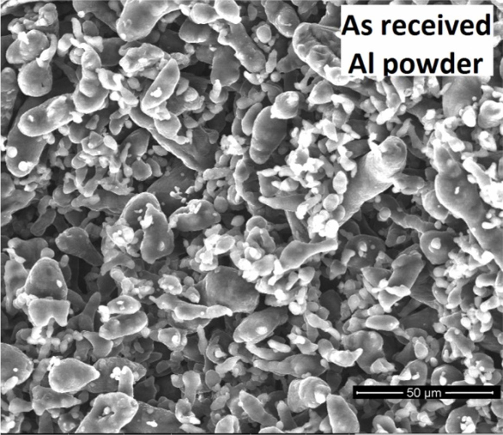
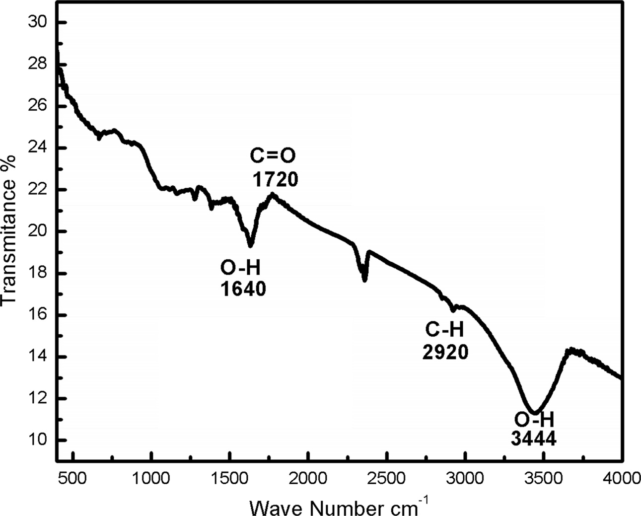
Aluminium powder of 20 µm particle size (Fig. 1) with 99.34% purity was used as matrix material and Multi-Wall Carbon Nanotubes (MWCNTs) having 8 nm diameter and 10-30 µm in length with purity 96.3%, was used as reinforcements in the present work. Prior to ball milling, the CNTs were refluxed in HNO3 using magnetic stirring to get the functional groups on side walls and ends of the CNTs. The functionalized CNTs were characterized by Fourier-transform infrared spectroscopy (FT-IR).
The Al-CNT composite powders were ball milled under the following conditions; Milling speed: 250 rpm, Time: 1, 6, 12, 18 and 24 hrs, ball to powder ratio of 10:1, wet milling with Toluene. The fabricated Al-CNT composite powder was characterized using SEM, XRD and Raman spectroscope. Then the fabricated composite powders were compacted and sintered at temperature 550℃ for 30 minutes. The hardness test was done on as-sintered Al samples and Al-CNT composites as per ASTM standard: E92 at a load of 0.300 kgf with dwell time of 10 seconds. The composites grains sizes were analyzed using the procedure described in ASTM E112–13.
|
Fig. 1 Fig. 1. SEM image of as received Al powder. |
The functionalization of CNTs leads to the formation of carboxylic groups on the side and ends of CNT surface. The FT-IR spectroscopic analysis is shown in Fig. 2 which reveals the peaks related to carboxyl and hydroxyl groups. The C-H and O-H stretching vibrations are observed between 2900 and 3500 cm-1. These functional groups present in the CNTs tend to reduce the agglomeration and improves the distribution of CNTs in the matrix [5]. The corresponding peaks for carboxylic bonding are C=O, C-H and O-H which are detected at wave numbers of 1,640, 2,920 and 3,444 cm-1 respectively [11, 12]
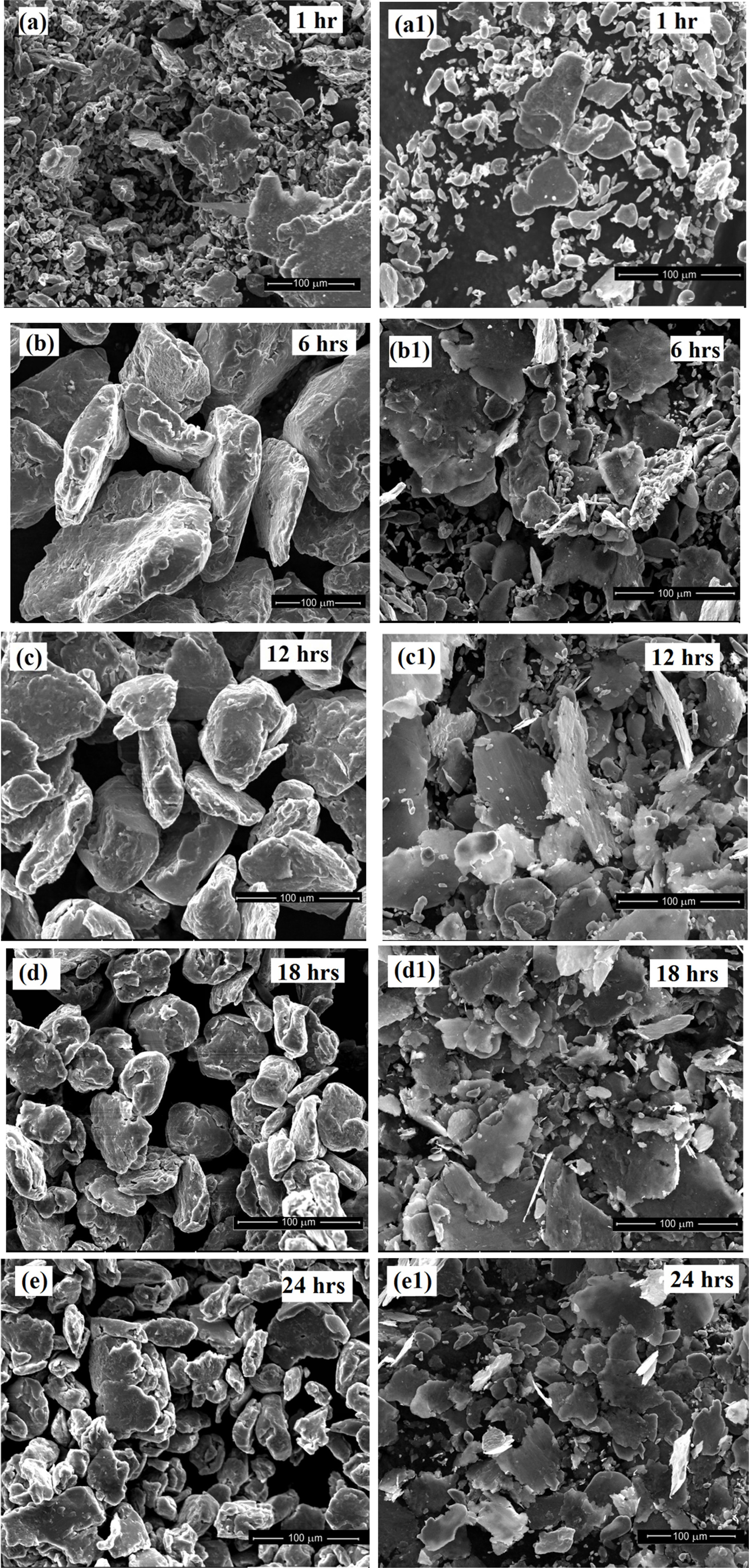
The Fig. 3 shows SEM images of the ball milled Al powders and Al-CNT powders morphology with varying ball-milling time. During the milling of pure Al, spherical morphology of the powders is flattened to flake shape between 6 and 12 hrs. This is due to the shearing effect of the balls [6, 18]. The larger surface area was obtained in the 6 hrs ball-milling when compared to other ball milling time (Fig. 3b). This would be helpful to attach the large aspect ratio CNTs uniformly to enhance the mechanical properties in resulting composites. However, as the ball milling time was increased beyond 12 hrs, the Al powders were further fractured and formed an irregular shape, as shown in Fig. 3d). This is due to cold working and fracturing of powders [13]. Also dispersion of the MWCNTs in the spherical Al powder can be observed with varying ball-milling times.
The SEM micrograph in Fig. 3(a1-e1) shows the surface regions of the Al-CNT composite powders at various time intervals of ball milling. It has been observed that the surface of the Al powder is covered with CNTs. As compared to pure Al samples the cold welding and fracturing of powders not been observed at prolonged milling time due to incorporation of CNTs.
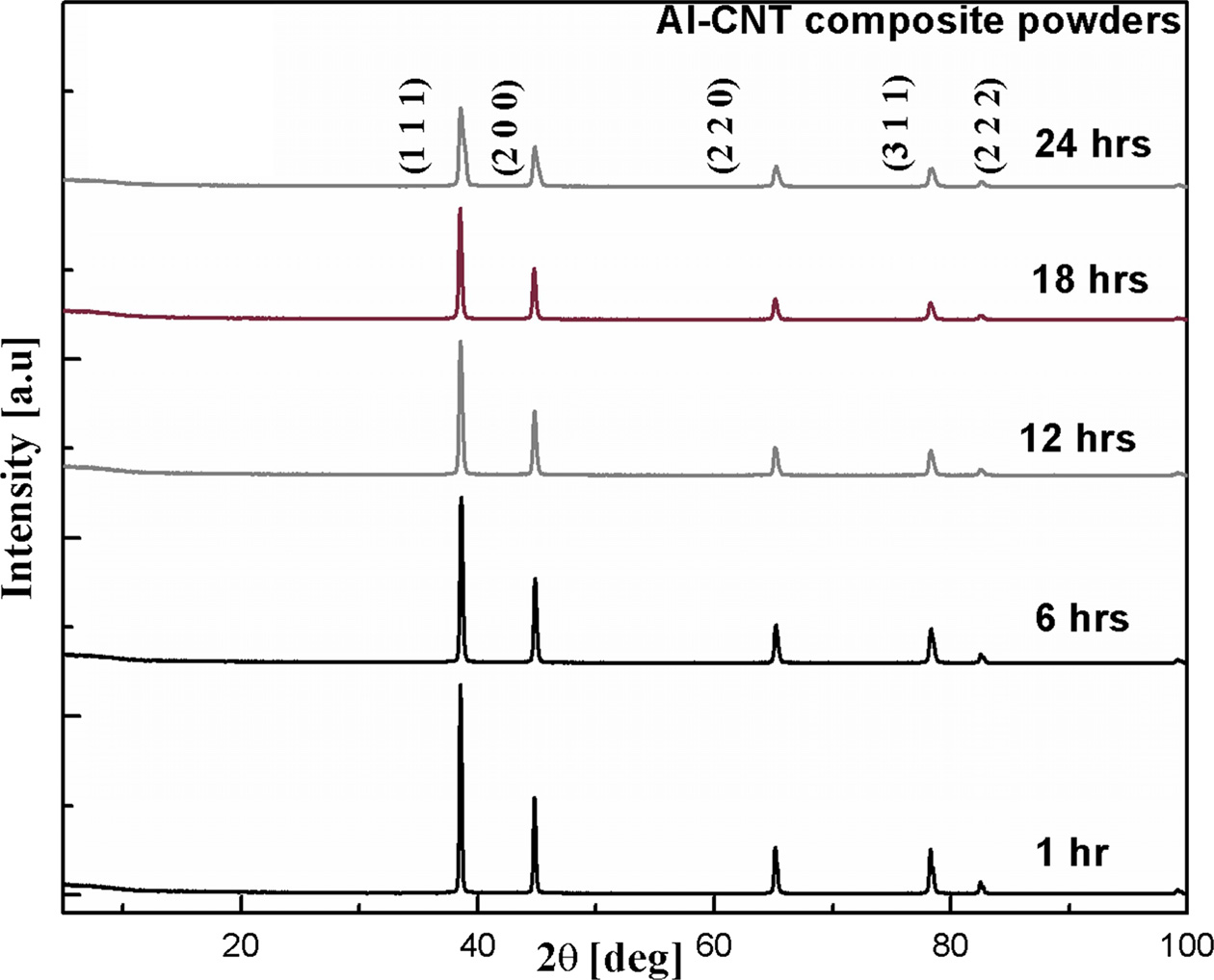
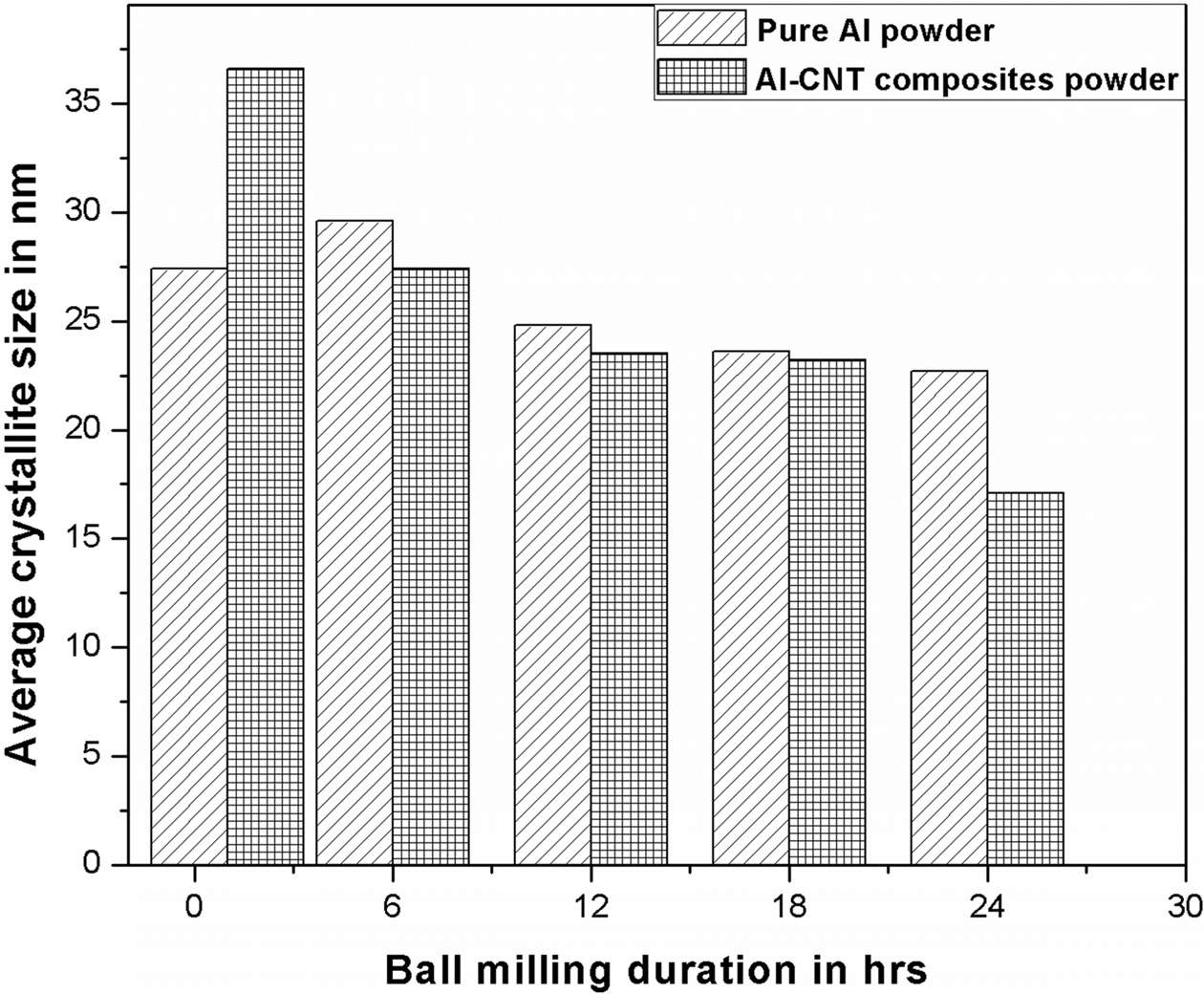
XRD analysis of composite powder (Fig. 4) is carried out to study the influence of ball milling time on the grain size of the ball milled Aluminium powder and Al-CNT composite powders, since grain size reduction helps to get more denser composites with increased mechanical properties. It is clearly visible that the peak intensity of ball milled Al-CNT samples become lowering and broadening with extended ball milling time. This is due to the grain refinement and induced strain by the ball milling process [13].
The average grain size is calculated using Scherrer Equation. Fig. 5 shows the average grain size of the ball milled samples for various ball mill times. It is clearly observed from the graph, the grain sizes of ball milled Al and Al-CNT powders shows that the increased ball milling time reduces the grain sizes of the particle [14, 15]. The mechanical properties of composites would be increased due to the decreased grain size of the composite powders [16].
|
Fig. 2 Fig. 2. FT-IR graph showing functional groups present in functionalized CNTs. |
|
Fig. 3 Fig. 3. SEM micrographs showing the morphology of ball milled pure Al powder (a-e) and Al-CNT (a1-e1) composite powder. |
|
Fig. 4 Fig. 4. XRD analysis of ball milled Al-CNT composite powders. |
|
Fig. 5 Fig. 5. Average crystallite size of ball milled samples calculated using Scherrer Equation. |
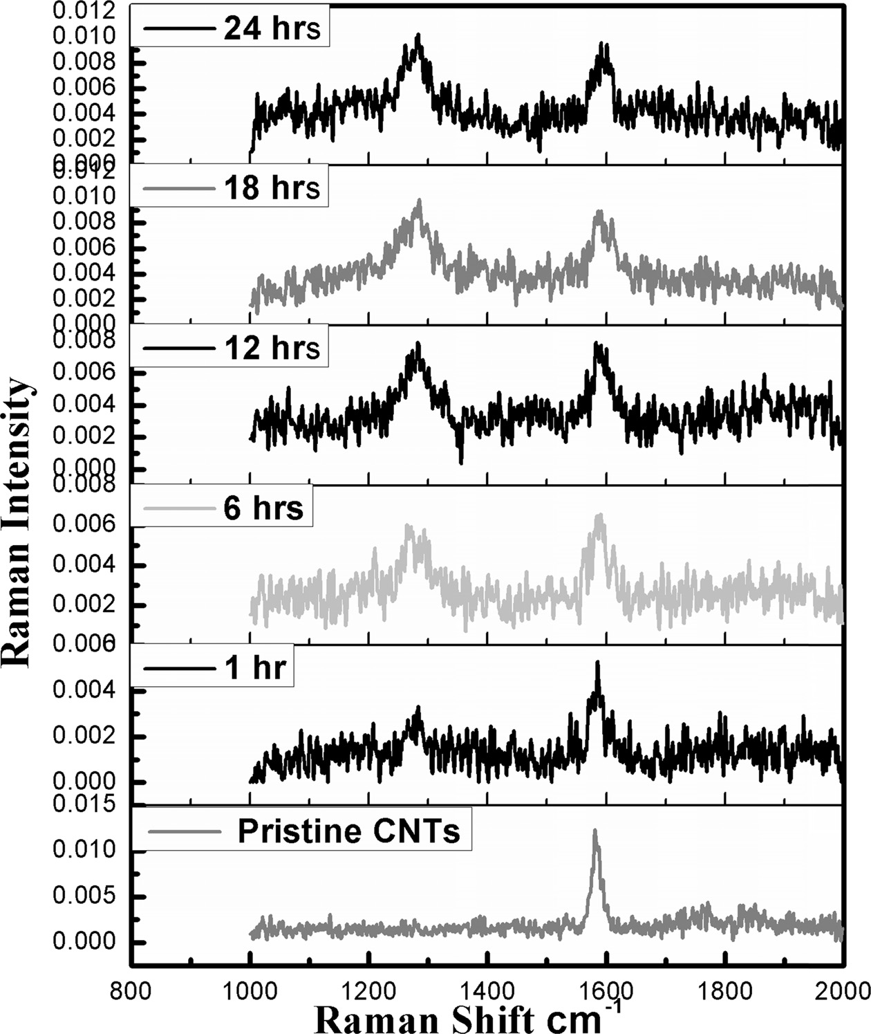
The Raman spectra analysis of composite powders is shown in Fig. 6. The D and G, Raman shifts are observed to characterize the structural quality of the nanotubes. The G (graphitic) band is observed around wave number 1,600 cm-1 commonly taken as reference to ensure the graphitic structure. Increased ball milling time induces more structural defects in CNTs which decreases graphitic intensity peak and widen. The D (defect) band, which represents defects in the CNTs graphitic structure, is found around wave number 1300 cm-1 [10].
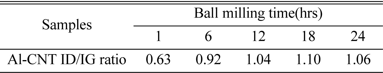
The intensity ratio between the two peaks D/G is a measure of the structural quality of MWCNTs. The G band and D band are attributed due to in-plane vibrations of SP2 carbon atoms and out of plane vibrations attributed to the presence of structural defects respectively. The Table 1 shows intensity ratio between the two peaks D/G. From the ratios it is clearly observed that the increased ball milling time gives the larger ID/IG values.
|
Fig. 6 Fig. 6. Raman spectra analysis for Ball milled Al-CNT powders. |
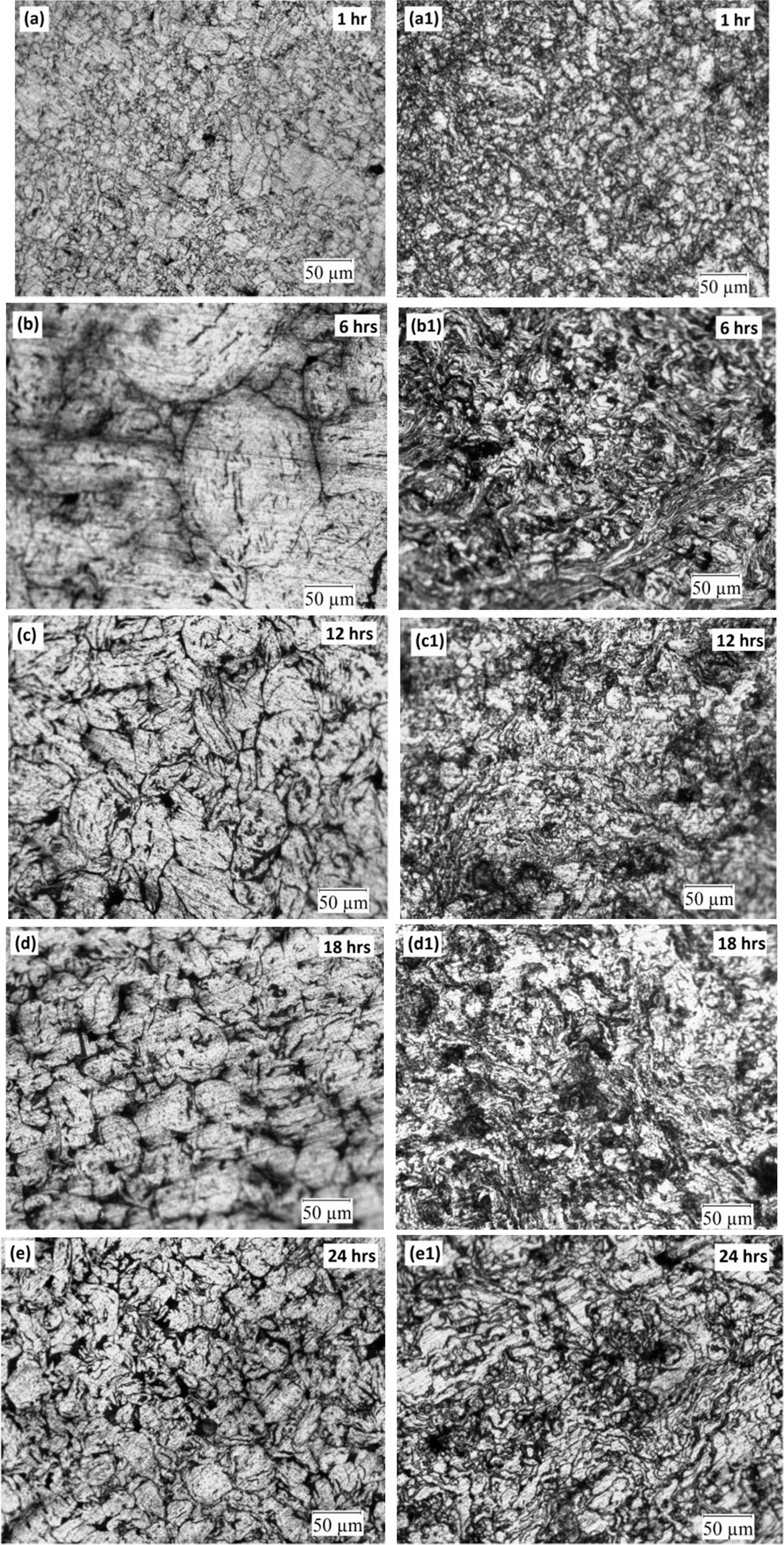
The microstructure of the as-sintered Al and Al-CNT
composites with varying ball milling time is shown in Fig. 7. It is evident
that addition of CNTs in to the Al matrix refines the grain size when compared
to pure Al samples. Also increase of the ball milling duration resulted
in decreased grain size of the composites. It is evident
from the microstructure grain size analysis the number of grains obtained for
Al-CNT composites by varying milling time of 1, 6, 12, 18 and 24 hrs are 800,
1,639, 2,432, 2,437 and 2,454 respectively. The grain refinement at particularly
in Al-CNT composites may be attributed to the larger strain due to the addition
of CNTs in to the matrix and improved dispersion of CNTs can significantly
inhibit the grain growth during sintering [17].
|
Fig. 7 Fig. 7. Optical Micrographs of as-sintered Al (a-e) and Al-CNT (a1-e1) composites by varying ball milling time. |
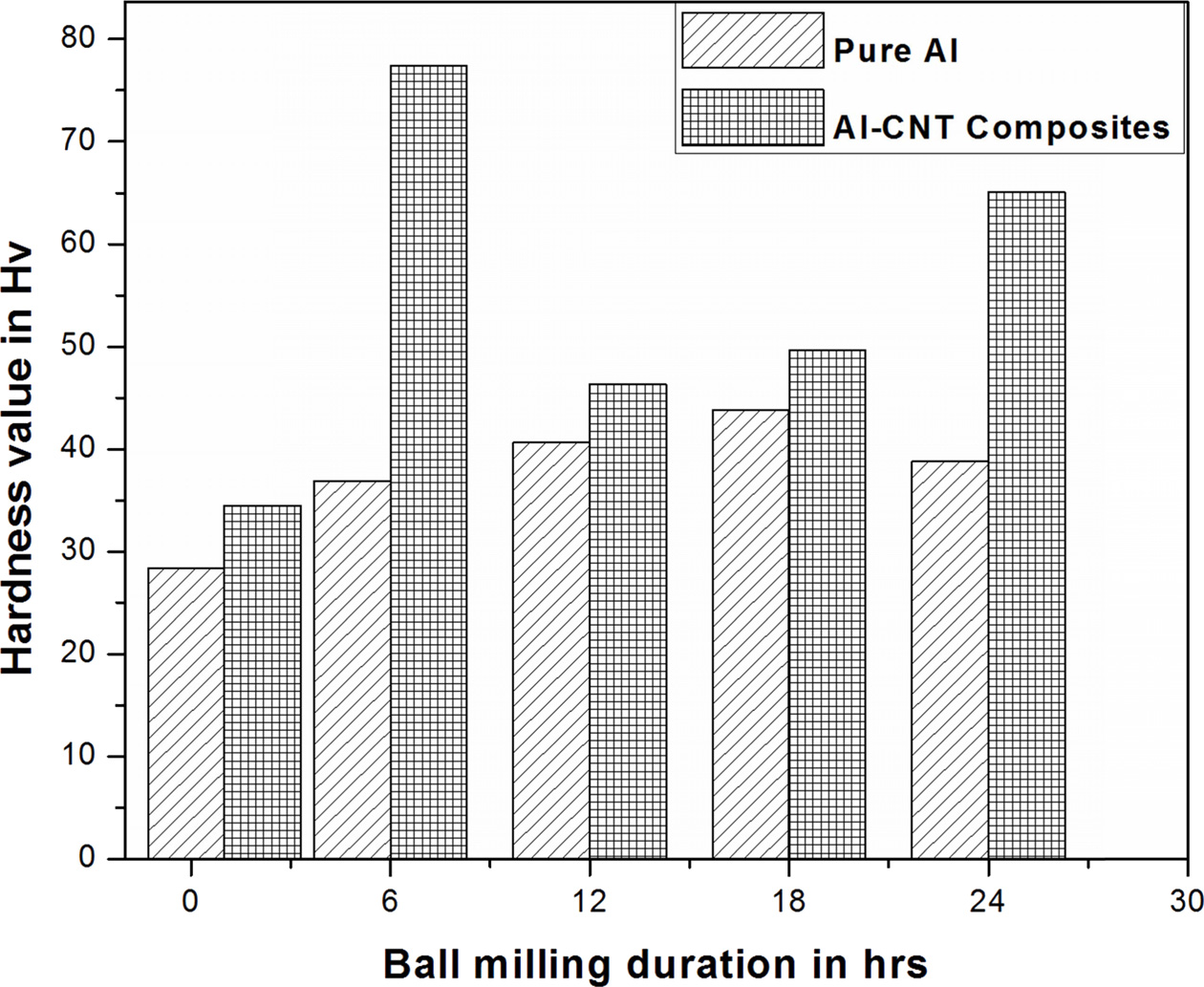
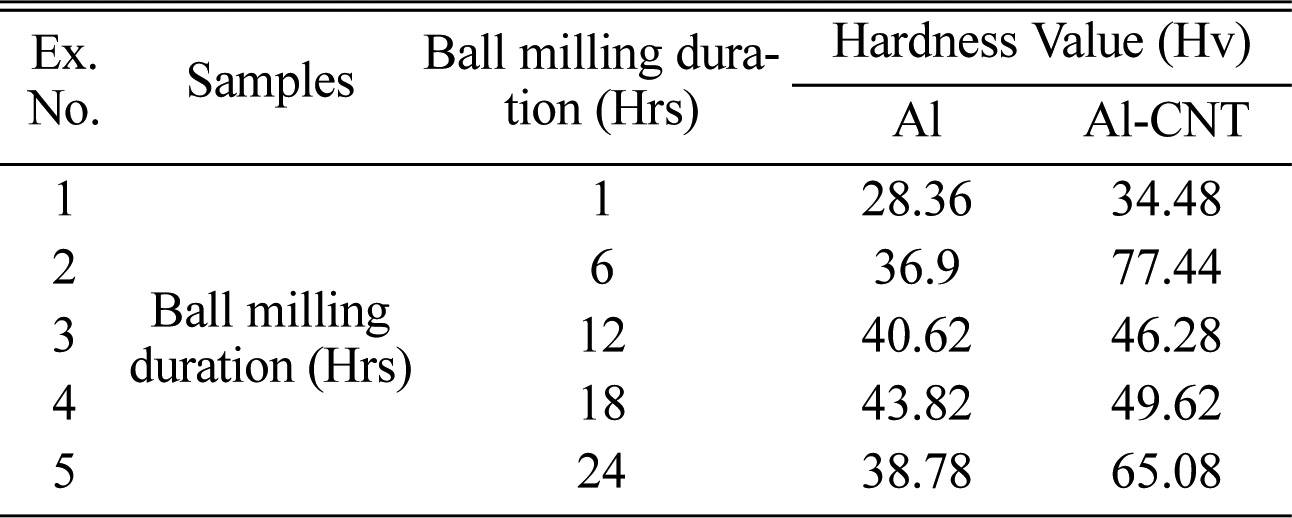
The Vickers hardness of the fabricated composites was
measured at room temperature which is shown in Table 2 and plotted in Fig. 8.
From the results, it is observed that the average Vickers hardness of Al/CNT
composites is increased from 34 Hv to 77.4 Hv. This increase in hardness value
was attributed due to the addition of CNTs when compared to pure Al samples whose
values ranging from 28.4 to 43.8 Hv. The highest hardness value (77.4 Hv) was
observed for 6 hrs ball milled Al-CNT composite. The results were compared with
various methods followed other researchers. Kim et al. obtained the
hardness values between 52-55 Hv for 1, 3 and 5 wt% of CNTs using
acid treatment and ultrasonication method [18], and Hansang Kwon et.al used
nano scale dispersion method and achieved the hardness value of 52 Hv for 5
vol% of CNTs [19]. A.M.K. Esawi et.al used ball milling method to
produce Al-CNT composites obtained hardness value of 75 Hv for 2
wt% of CNTs [20], Mina M.H. Bastwros et.al obtained hardness value of 84.5 Hv
for 2.5 wt% of CNTs using ball milling method [21].
During 6 hrs of ball milling, the Al and CNT composite
powders were flatten by shearing force (Fig. 3b1), attributed to increased
specific surface area, due to which more anchoring sites for CNTs were
obtained. Increase in ball-milling time resulted in gradual decrease
in structural stability of CNTs and leads to reduced mechanical properties. It
is evident from the study, for 6 hrs sample the hardness value of
77.4 Hv was obtained with ID/IG value of 0.92. Whereas the hardness of
12 hrs sample is 46.2 Hv having ID/IG ratio of 1.04. Hence the structural
defects of CNTs greatly influence the mechanical properties of the resulting
composites [22, 23]. It is also observed from the results that the grain
size of the Al-CNT powder (17.1 nm) is less than that of pure Al powder (22.7
nm) at 24 hrs of extended ball milling. The grain refinement due to presence of
CNTs in composite powder may be the reason for higher hardness [15]. A
threefold increase in hardness values were observed in Al-CNT composites than
that of pure Al samples. The ID/IG ratio of CNTs increases with increased ball
milling time, it was found that for 6 hrs ball milling the ID/IG values are
less compared to the subsequent samples. The 24 hrs ball milled sample ID/IG
value was observed as 1.06. Even though these values are higher than that of
0.6 (1 hr), the increased hardness is due to uniform distribution of CNTs in
the matrix and grain refinement.
|
Fig. 8 Fig. 8. Hardness of Pure Al and Al-CNT composites by varying ball milling time. |
In the present study, ball-milling process was used to
fabricate the Al-CNT composite powders. During ball milling process between 6
and 12 hrs, the shearing effect of the balls flatten spherical morphology of Al
powder to flaky shape. The hardness of 77.4 Hv was observed in 6 hrs ball
milled Al-CNT composite. This increase in hardness values is mainly attributed
to increased specific surface area, due to which more anchoring sites for CNTs
were obtained. The Raman spectra analysis of composite powders indicates the
quality of the nanotubes. Due to the prolonged ball milling the ID/IG of CNTs
varied from 0.6 to 1.06. The increase in ball milling time resulted in higher
values of ID/IG ratios.
The hardness of 12 hrs Al-CNT sample is 46.2 Hv, and
having ID/IG ratio of 1.04. Hence, longer milling duration caused decrease in
structural stability of CNTs and greatly influences hardness of composites.
Even though the ID/IG ratio of 24 hrs ball milled Al-CNT composite is higher
than that of 1 hr milled sample, the increased hardness is due to uniform
distribution of CNTs in the matrix and grain refinement.
We acknowledge the Nanotechnology Research Centre, SRMIST for the utilization of FE-SEM and XRD facility.
- 1. S. Iijima, Nature, 354 (1991) 56-58.
-

- 2. V.N. Popov, Materials Science and Engineering, R 43 (2004) 61-102.
-
- 3. E. Neubauer, M. Kitzmantel, M. Hulman, and P. Angerer. Composites Science and Technology 70 (2010) 2228-2236.
-
- 4. S. R. Bakshi, D. Lahiri, and A. Agarwal, International Materials Reviews 55 (2010) 41-64.
-
- 5. S.K. Singhal, R. Pasricha, S. Teotia, G. Kumar, and R.B. Mathur, Composites Science and Technology 72 (2011) 103-111.
-
- 6. A. Esawi and K. Morsi, Composites: Part A 38 (2007) 646-650.
-
- 7. Z.W. Xue, L.D. Wang, P.T. Zhao, S.C. Xu, J.L. Qi, and W.D. Fei, Materials and Design, 34 (2012) 298-301.
-
- 8. J.-l. Song, G.-Y. Lee, J.-r. Kim, and J.-S. Lee, Journal of Ceramic Processing Research 19[4] (2018) 279-284.
-
- 9. C.W. Park, J.H. Lee, S.H. Kang, J.H. Park, H.M. Kim, H.S. Kang, H.A. Lee, J.H. Lee, J.H. In, and K.B. Shim, Journal of Ceramic Processing Research 19[2] (2018) 179-182.
-
- 10. M.T.Z. Hassa, A.M.K. Esawi, and S. Metwalli, Journal of Alloys and Compounds 607 (2014) 215-222.
-
- 11. A.G. Osorio, I.C.L. Silveira, V.L. Bueno, and C.P. Bergmann, Applied Surface Science 255 (2008) 2485-2489.
-
- 12. F. Rikhtegar, S.G. Shabestari, and H. Saghafian, Journal of Alloys and Compounds 723[5] (2017) 633-641.
-
- 13. X.-n. Hao, H.-p. Zhang, R.-x. Zheng, Y.-t. Zhang, K. Ameyama, and C.-l. Ma, Transactions of Nonferrous Metals Society of China 24 (2014) 2380-2386.
-
- 14. H.J. Choi, J.H. Shin, and D.H. Bae, Composites Science and Technology 71 (2011) 1699-1705.
-
- 15. M. Raviathul Basariya, V.C. Srivastava, and N.K. Mukhopadhyay, Materials and Design 64 (2014) 542-549.
-
- 16. T. Varola and A. Canakci, Powder Technology 246 (2013) 462-72.
-
- 17. C.D. Li, X.J. Wang, W.Q. Liu, K. Wu, H.L. Shi, C. Ding, X.S. Hu, and M.Y. Zheng, Materials Science & Engineering A 597 (2014) 264-269.
-
- 18. I.-Y. Kim, J.-H. Lee, G.-S. Lee, S.-H. Baik, Y.-J. Kim, and Y.-Z. Lee, Wear 267 (2009) 593-598.
-
- 19. H. Kwon, M. Estili, K. Takagi, T. Miyazaki, and A. Kawasaki, CARBON 47 (2009) 570-577.
-
- 20. A.M.K. Esawi, K. Morsi, A. Sayed, M. Taher, and S. Lanka, Composites Science and Technology 70 (2010) 2237-2241.
-
- 21. M.M.H. Bastwros, A.M.K. Esawi, and A. Wifi, Wear 307 (2013) 164-173.
-
- 22. Z.Y. Liu, S.J. Xu, B.L. Xiao, P. Xue, W.G. Wang, and Z.Y. Ma, Composites: Part A 43 (2012) 2161-2168.
-
- 25. H.J. Choi, J.H. Shin, and D.H. Bae, Composites: Part A 43 (2012) 1061-1072.
-
 This Article
-
2019; 20(5): 505-511
Published on Oct 31, 2019
- 10.36410/jcpr.2019.20.5.505
- Received on Apr 30, 2019
- Revised on Jul 22, 2019
- Accepted on Jul 24, 2019
Services
- Abstract
introduction
experimental procedure
results and discussion
conclusion
- Acknowledgements
- References
- Full Text PDF
Shared
Correspondence to
- R. Murugesan
-
Department of Mechanical Engineering, Faculty of Engineering and Technology, SRM Institute of Science and Technology, Kattankulathur, Tamilnadu, India – 603203.
Tel : +919445126532 - E-mail: murugesan.r@ktr.srmuniv.ac.in
Clean-Energy Research Institute(CRI), Hanyang University, 222, Wangsimni-ro, Seongdong-gu, Seoul, 04763, Korea
E-mail: jcpr@hanyang.ac.kr