


- Effect of coating thickness on contact fatigue and wear behavior of thermal barrier coatings
Dong Heon Leea, Bin Jangb, Chul Kimb and Kee Sung Leeb,*
aDepartment of Automotive Engineering, Kookmin University, Seoul, Korea
bSchool of Mechanical Engineering, Kookmin University, Seoul, Korea
The effect of coating thickness on the contact fatigue and wear of thermal barrier coatings (TBCs) are investigated in this study. The same bondcoat material thickness (250 μm) are used for each sample, which allows the effect of the coating thickness of the topcoat to be investigated. TBCs with different coating thicknesses (200, 400, and 600 μm) are prepared by changing processing parameters such as the feeding rate of the feedstock, spraying speed, and spraying distance during APS(air plasma spray) coating. The damage size on the surface are strongly affected by the coating thickness effect. Although the damage size from contact fatigue using a spherical indenter diminish at a TBC of 200 μm, a high wear resistance such as a low friction coefficient and little mass change are found at a TBC of 600 μm. These results indicate that the coating thickness strongly affects the mechanical behavior in TBCs during gas turbine operation.
Keywords: Gas turbine, Thermal barrier coating, Coating thickness, Contact fatigue, Wear
Air-plasma-sprayed yttrium-stabilized zirconia (YSZ) is a popular material for gas turbine coating because of its high thermal and mechanical stabilities and good thermal expansion coefficient compared to those of metal submaterials. The lower thermal conductivity of YSZ is beneficial as a high-heat insulation during gas turbine operation at high temperatures above 1100 ℃ [1-4].
Although the thermal insulation provided by the thermal barrier coating (TBC) is one of the parameters for determining the lifetime of a coating, the coating is also used to protect a superalloy substrate against mechanical damages from the mechanical fatigue stress caused by vibration or wear and the erosion caused by foreign objects. Fractures from notches or indents can occur in TBCs, even though most failures occur as a result of the interface delamination caused by thermal grown oxide formation between the TBC and bondcoat [1, 3-4].
TBCs with different coating thicknesses are used for different applications such as an E- (1100 ℃) or F-class (1350 ℃) gas turbine. However, most of studies investigate thermal degradation rather than mechanical degradation of TBCs [1, 2]. The systematic study is needed to investigate the effect of coating thickness on the wear and fatigue properties. The coating thickness can be controlled by adjusting parameters such as the feed rate, gun distance, and gun speed during plasma-sprayed coating. Selective coating thicknesses of 200, 400, and 600 mm were obtained in this study.
Hertzian indentations using a spherical indenter were used to evaluate the contact fatigue resistance of the coatings, as well as those of free standing materials [4-6]. The damages produced on the surfaces were examined using an optical microscope under Nomarski illumination. This evaluation helps to understand the mechanical behavior of TBCs by FOD(foreign object damage). Prior results showed that the contact fatigue behavior critically depends on the microstructures of a specimen, with particularly harmful effect seen for relatively larger and elongated grains. The accumulation of multiple fatigue cycles causes material collapse at critical cycles by radial cracks. A model for cyclic contact fatigue in tough and quasi-plastic ceramics such as TBC materials (YSZ) was established [7].
Wear is a more complicated action on the surface of a coating than indentations. The wear rate and friction coefficients of the coatings were evaluated using a ball-on-disk method in this study. Balls with the same radius were used for damage and wear tests, but under different contact loads.
Although air plasma spraying is generally used for coating in the gas turbine industry, the effect of the coating thickness, particularly against wear and damage properties, has not been determined. Some results have indicated that a coating design without optimization causes severe failures [8, 9]. Therefore, the aim of the present study was to evaluate the wear and damage properties of TBCs with different coating thicknesses.
Substrates with a diameter of 25.4 mm and a thickness of 2 mm were machined from a Ni-based superalloy (Hastelloy-X) using an electro-discharge machining process. The samples were ground and sand-blasted to improve their adhesion ability. We deposited a Ni-Cr-Co-Al-Y alloy (AMDRY 9625, Sulzer Metco Co., Switzerland) bondcoat material on the substrates using an HVOF process. The thickness of the bondcoat was maintained at d = 250 ± 30 μm. Finally we deposited YSZ (8 wt% Y2O3 stabilized zirconia, METCO 204CNS, Sulzer Metco Co., Switzerland) on the bondcoat using an air plasma spray (APS) gun (Triplex 200, Sulzer Metco Co., Switzerland). The coating thickness of the topcoat was varied (200, 400, and 600 μm) by changing the powder feed rate, gun speed and spray distance. The ranges of the varying parameters in the APS coating apparatus are listed in Table 1. The topcoats of the samples were ground and polished using 6-μm, 3-μm, and 1-μm diamond pastes, consecutively.
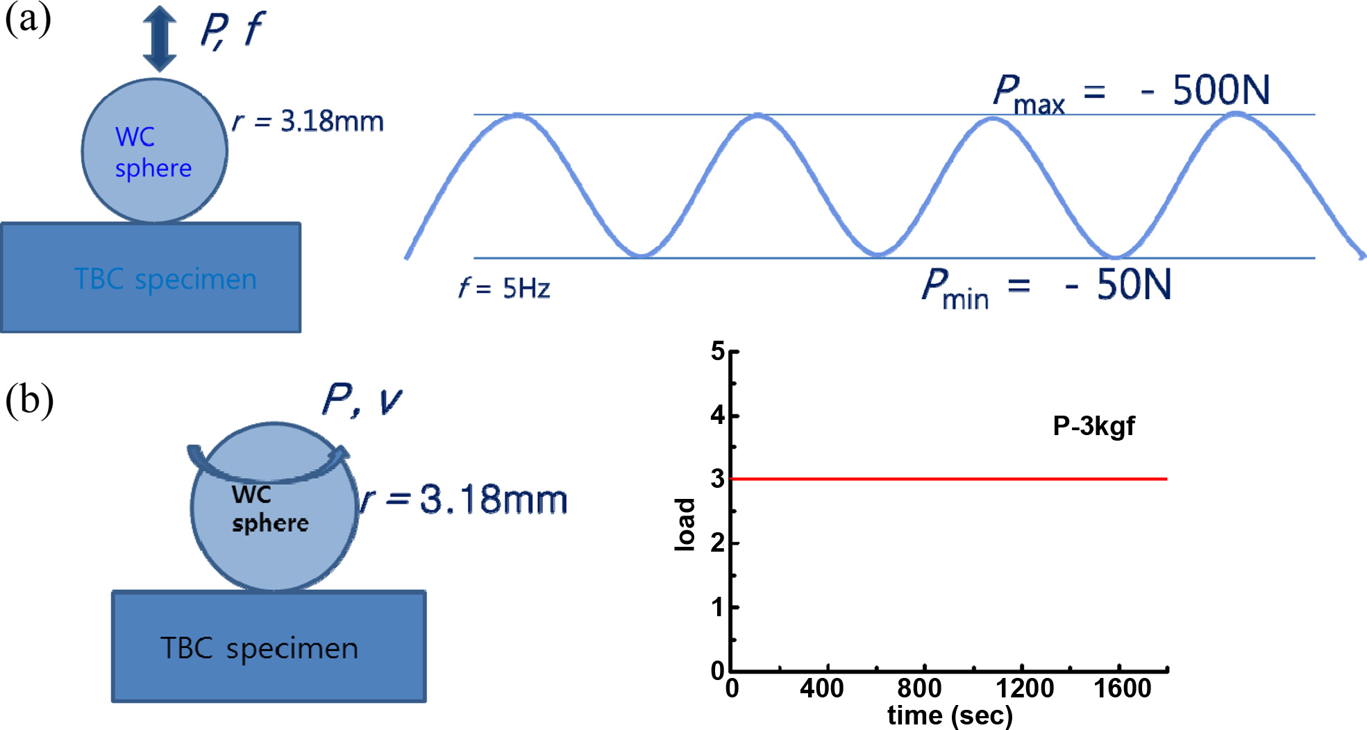
Cyclic contact tests (Model 8841, Instron, USA) were conducted by indenting the topcoat surface using a ball at load P = 500 N in air. The indentations were applied periodically to the coating surface using a sine wave with a frequency f = 5 Hz. The number of cycles was varied (n = 103, 104 and 105), and the indentations were made using a tungsten carbide (WC) ball with radius r = 3.18 mm. The position of each point of contact between the indentation ball and the coating surface during indentation was detected in the fatigue apparatus. The surface damages were observed using an optical microscope under Nomarski illumination.
The wear test was conducted using the same tungsten carbide ball used in the contact fatigue test, but the load was changed to P = 30 N because the test conditions in the wear test were very severe. Ball-on-disk methods were selected in this study, in which a ball rotates at a constant speed (v = 600 rpm) for 1800 s on a fixed disk sample bonded to a stainless jig along a constant circular trace with a radius of 10 mm. The friction coefficients were calculated by measuring the friction loads for each cycle under a constant normal force. The wear loss was calculated by comparing the weights before and after the wear tests were conducted. The wear scars produced on the surface of the topcoat were observed using an optical microscope.
Schematic diagrams of the cyclic contact tests and wear tests are shown in Fig. 1. Note that the cyclic contact tests were conducted by loading the ball along the z-axis, whereas the wear tests used two-dimensional motion if we ignore the wear loss along the z-axis. The load changes as a function of the testing time are also included in the figure. Whereas the cyclic fatigue test was conducted using loadings with a sine wave profile, a constant load acted on the sample in the wear test.
|
Fig. 1 Schematic diagrams of (a) cyclic contact fatigue test and (b) wear test using ball-on-disk method. The representative load change profiles as a function of the testing time are also shown. |
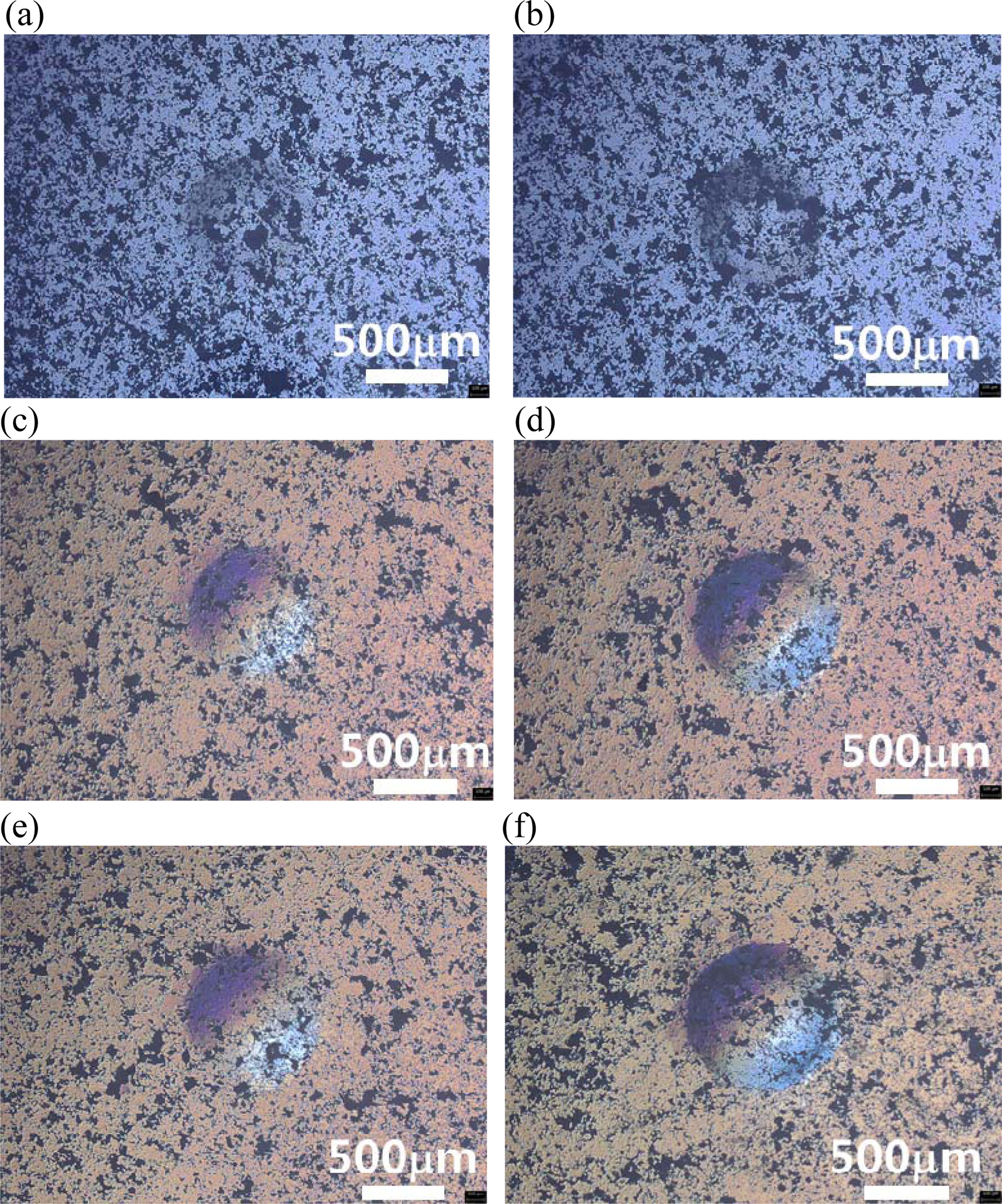
The surface damage morphologies from the contact fatigues in the TBCs with different coating thicknesses (200, 400, and 600 μm) produced by a loading of P = 500 N for n = 103 and 105 at f = 5 Hz using a 3.18-mm WC ball are shown in Fig. 2. Quasi-plastic surface damages are evident in this thermal barrier material. No macroscopic ring cracks are observed around the contact sites, because the YSZ material produces an extensive yield zone consisting of microcracks rather than cone cracks beneath the contact sites under the contact load. Previous studies have reported that this type of quasi-plastic damage in zirconia thermal barrier materials manifests as a cloud of closed shear microcracks or shear faults within a shear-compression deformation zone above a critical point under the critical load [10, 11]. The size of the damages increased with an increase in the number of cycles, from n = 103 to n = 105, irrespective of the coating thickness. However, the damages were less evident in the TBCs with a coating thickness of 200 μm.
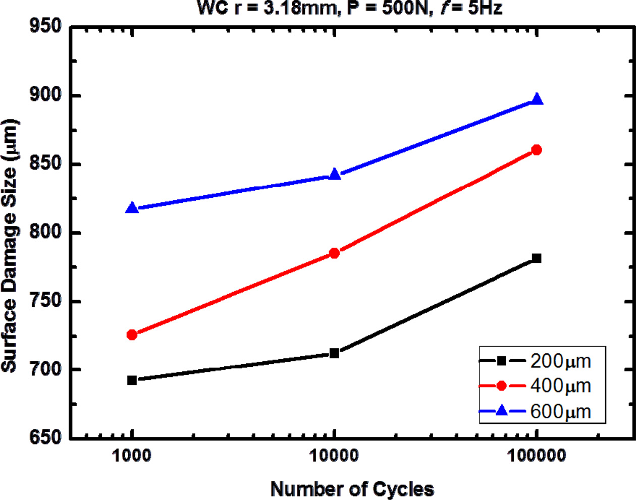
The plots of the size of the contact damages produced from the indentation fatigues on the TBCs with different coating thicknesses are shown in Fig. 3. The diameters of the circular damages, as shown in Fig. 2, were measured using an image analysis and plotted as a function of the coating thickness in the figure. The solid line is the fit of the experimental data. The results indicate that the size of the surface damage obviously increases with an increase in the number of cycles. Therefore, this foreshadows the damages such as wear loss that can occur to TBCs from contacting particles under the vibrating conditions of a gas turbine machine. The sizes of the contact damages were larger at barrier coatings thicker than 200 μm.
Our previous work suggested that the results could be inferred from the subsurface role [8, 11]. The damage sizes in the coatings exceeded the coating thicknesses, as shown in Fig. 2. Thus, the mechanical properties of the subsurface influenced the damage patterns in the coatings. It has been reported that the elastic modulus of the bondcoat is stiffer than that of the TBC. We reported the indentation stress–strain curve of each component of a TBC system, such as the substrate, bondcoat, and coating material, after thermal fatigue for 20 and 100 h at a temperature of 1100 ℃ [11]. The stress-strain curve was not affected by thermal fatigue. Therefore, we can ignore its effect. If we compare the mechanical behaviors of the indentation stress–strain curves based on the above assumption, the curve plots indicate that the bondcoat material showed stiffer mechanical behavior than the coating material in the literature. We also demonstrated that the contact-induced damages were critically influenced by the subsurface in a bilayer structure [8]. In coating layers containing stresses caused by different elastic modulus values for each layer in a bilayer structure, the stress in the coating layer can be changed by the subsurface effect. In this study, the coating thickness is one of the most important controllable variables in this bilayer structure in relation to designing a high damage tolerance.
It is conjectured that the damages in TBCs with thinner coating thicknesses are affected to a greater extent by the subsurface. Thus, the sizes of the damages were relatively smaller at the 200-mm coating. Even though the porosity values are not exactly the same for TBCs with different thicknesses, as shown in Fig. 2, which affects the damage distributions (note that the total porosity of the coatings is the highest among the three materials) [12], it is thought that the role of the subsurface is more critical in the surface impression results after unloading the indentation.
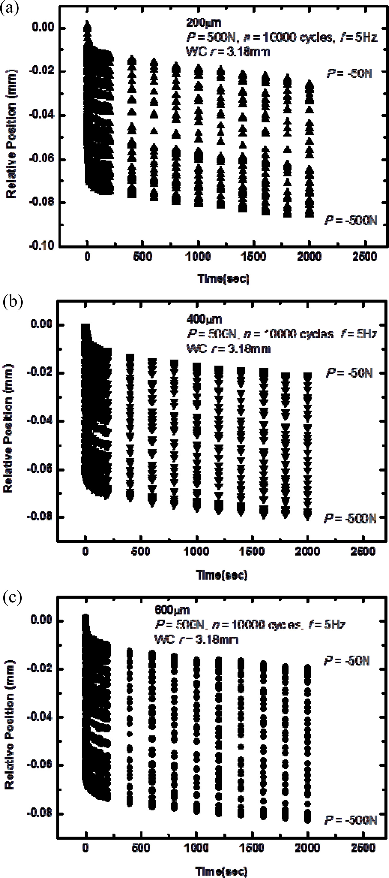
Fig. 4 compares the relative positions of each contact point of the WC ball (with radius r = 3.18 mm) on the TBCs with different coating thicknesses (200, 400, and 600 μm) at indentation cyclic loads from 50 N to 500 N at f = 5 Hz for 10,000 cycles. The ball moved downward from 18 μm to 86 μm from the top contacts at the different cyclic loads.
The diminishing data for the relative positions at each load P = -50 N for each time indicates that wear occurred during the contact cycling loads under the given conditions. It is evident that permanent residual deformation on the surface formed after unloading, as shown in Fig. 2. Although the diameter of the contact damages produced on the surface of the TBC was smaller, as shown in Fig. 3, the wear from the top contacts occurred more at a relatively thinner coating thickness (200 μm), as indicated in Fig. 4. In the comparison of the relative positions in the TBC with different thicknesses, the wear occurred sequentially at TBCs with thicknesses of 200 μm > 400 μm > 600 μm. These results showed an inverse dependence on the results in Fig. 3 because the relative position data at P = -50 N were not influenced by the subsurface. Ultimately, the final relative positions of the indentation ball showed that the data ranged from 18 to 25 μm, which were thinner than 1/10 of the respective coating thickness, indicating little influence from the mechanical properties of the subsurface (bondcoat in this study).
On the other hand, the relative positions of the final loadings (t = 2000 s) at P = -500 N were almost the same irrespective of the coating thickness. These results were probably caused by the resistances of both the coating and bondcoat materials. However, we could also detect a diminishing trend for the relative positions, even at load P = -500 N, indicating the wear occurrence.
The tribological properties of the TBCs with different coating thicknesses are shown in Figs. 5 and 6. The coatings are compared at the same load, P = 30 N, up to the same rotation cycles at room temperature.
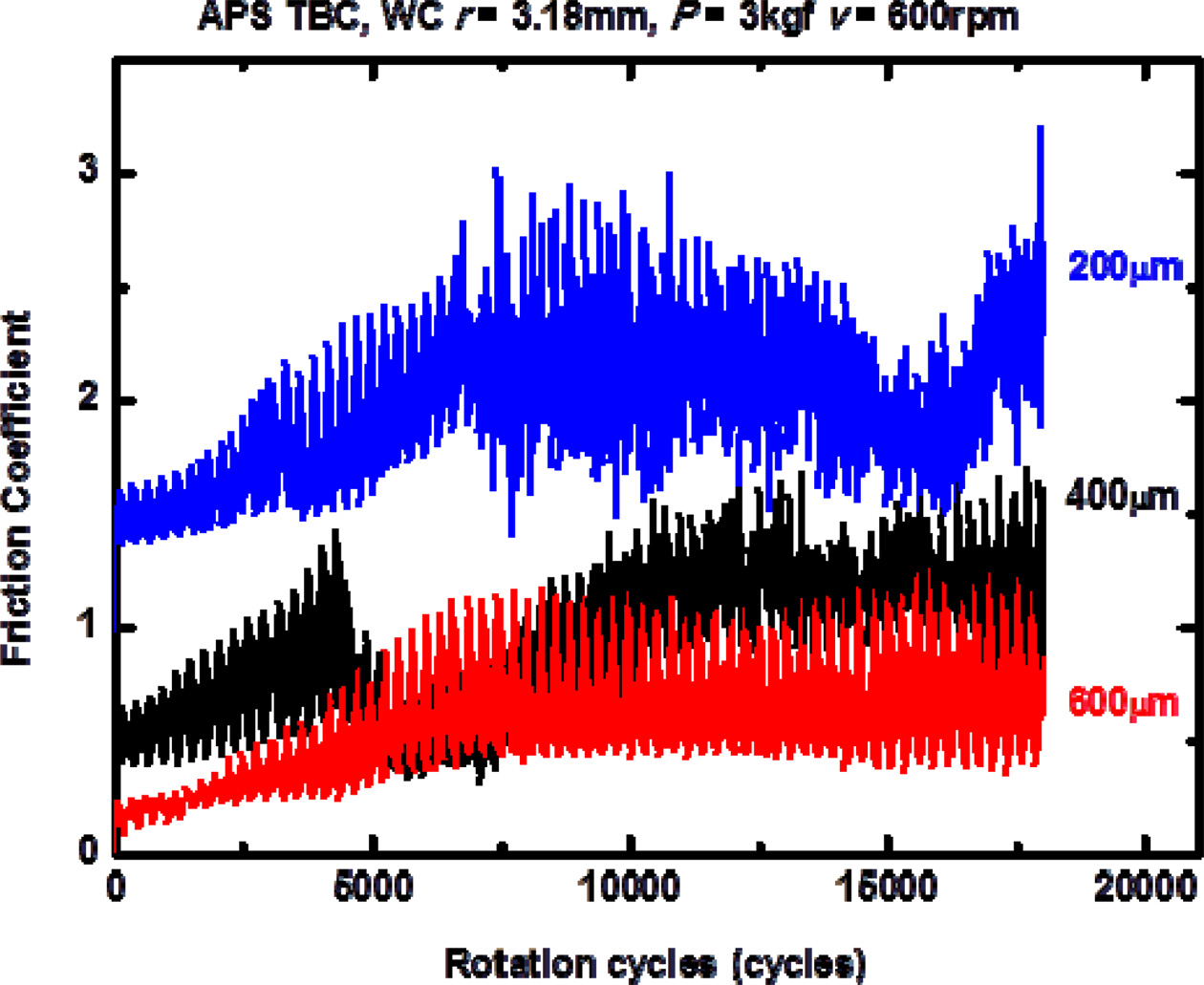
The friction coefficients for the three TBCs are comparatively shown in Fig. 5. Each friction coefficient curve shows an increasing tendency at the initial stage and then stabilizes at a specific constant value. This stabilization becomes smoother as the coating thickness of the thermal barrier increases. The three TBCs showed different coefficient values because of their porosities, as shown in Fig. 2, and the thickness effect. Whereas some decreasing tendencies and oscillation behaviors for the friction coefficient variations were found at TBCs of 200 and 400 μm, the 600-μm coating exhibited the lowest and most stable friction coefficient values among the three coating materials.
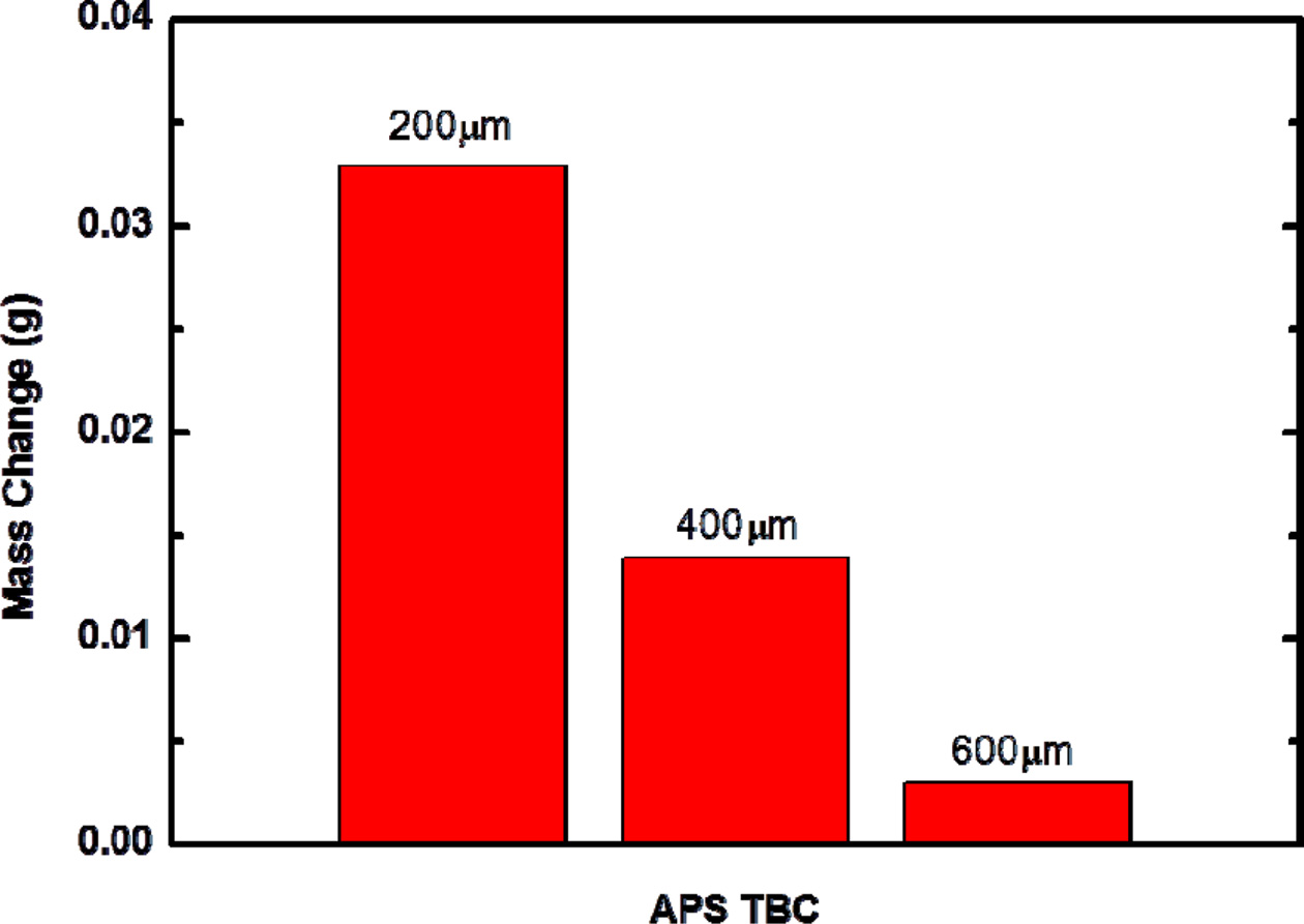
Fig. 6 shows a mass change comparison of the TBCs with different thicknesses, 200, 400, and 600 μm, during the wear test. Wear or erosion can make a TBC thinner, reducing the thermal insulation effectiveness [13, 14]. If the thickness of a TBC is thinned by wear, the bondcoat can be exposed to oxidation, which increases the possibility that the coatings will fail. The changes were compared to each other under the same wear condition. The variations in mass before and after wear suggest that the role of the coating thickness in volume removal by wear testing is important. The results indicate that the wear loss can be diminished by increasing the coating thickness. Our finding that the lowest friction coefficient and mass change occurred for the 600 μm TBC among the three materials suggests that a thicker coating within the given range is better for high wear resistance. It is notable that the indentation load of P = 30 N for the wear test was much lower than the load of P = 500 N used for the indentation test in this comparison.
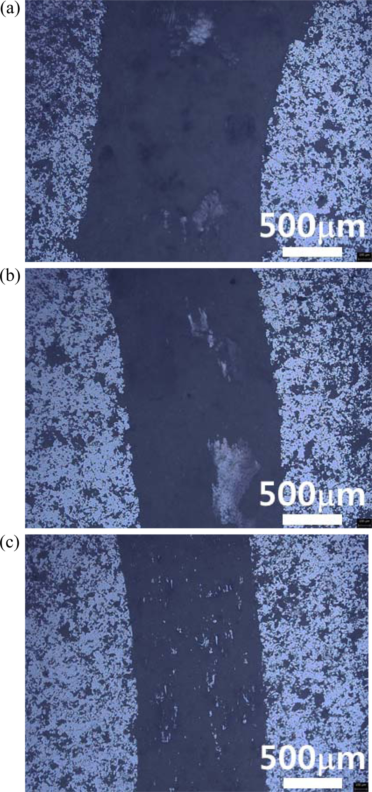
A quasi-ductile TBC is damaged by a harder and stiffer tungsten carbide ball, as shown in Fig. 7. The rotation of the ball under a constant and fixed load destroyed the coatings. The pictures show that abrasive wear occurs when a harder tungsten carbide surface slides on a softer YSZ material. On the other hand, the formation of macroscopic cracks was not observed, which suggests that the surface breakup occurred by the formation of microcracks. This micromechanism is consistent with the result for the quasi-plastic damage formation by Hertzian indentation shown in Fig. 2. The size of the wear scar depended on the thickness of the TBC. The width of the wear scar diminished as the thickness of the 
|
Fig. 2 Optical micrographs of indentation sites from loading at P = 500 N using WC ball with r = 3.18 mm, comparing damages in TBCs with thicknesses of (a) 200 μm, for n = 103; (b) 200 μm, for n = 105; (c) 400 μm, for n = 103; (d) 400 μm, for n = 105; (e) 600 μm, for n = 103; and (f) 600 μm, for n = 105. The tests were conducted in air at f = 5 Hz. |
|
Fig. 3 Surface damage sizes produced by contact fatigues using WC ball, r = 3.18 mm, under conditions of P = 500 N and f = 5 Hz. The diameters of the circular damages were measured and plotted as a function of the number of cycles, n = 103 and 104. |
|
Fig. 4 Relative positions of WC ball, r = 3.18 mm, during contact fatigues by sine waves, between P = 500 N (maximum indentation load) and P = 50 N (minimum indentation load) as function of testing time, comparing damages in TBCs with thicknesses of (a) 200 μm, (b) 400 μm, and (c) 600 μm for n = 104. The tests were conducted in air at f = 5 Hz. |
|
Fig. 5 Friction coefficient changes in TBCs as function of rotation cycles in wear test, using WC ball with radius of 3.18 mm at load P = 30 N and 600-rpm rotation speed for different coating thicknesses, 200, 400, and 600 μm, illustrating coating thickness effect in each graph. |
|
Fig. 6 Mass changes in TBCs as function of coating thickness in wear test, using WC ball with radius of 3.18 mm at load P = 30 N and rotation speed of 600 rpm for 18,000 cycles. Note that the mass change considerably decreases at a coating of 600 μm. |
|
Fig. 7 Optical micrographs of representative wear scars produced on surfaces of TBCs in wear test, using WC ball with radius of 3.18 mm at load P = 30 N and rotation speed of 600 rpm for 18,000 cycles. The wear scars were observed in the TBCs with different coating thicknesses: (a) 200, (b) 400, and (c) 600 μm. |
TBCs with different coating thicknesses were obtained by air plasma spraying a YSZ material for a gas turbine component. Because deformations or fractures can occur as a result of notches or indentations, indentation and wear tests were evaluated using a WC ball. The coating thicknesses were controlled (200, 400, and 600 μm) by varying parameters such as the feed rate, gun distance, and speed during the plasma spray coating. The damages formed on the surface appeared to be quasi-plastic without any macroscopic cracks, and the damage and wear resistance of the TBCs depended on the coating thickness. The TBC with a coating thickness of 600 μm showed the lowest friction coefficient and mass change during the wear test, indicating a high wear resistance.
This work was supported by IT R &D program of MOTEI/KEIT (20000192, Development on the crack healing technology of CMC composite and coating material for gas turbine hot gas component). Professor Yeon-Gil Jung in Chanwon University assisted with the coating experiment.
- 1. S. Bose, in “High Temperature Coatings. Burlington” (MA USA, 2007) p. 162-183.
- 2. R.W. Trice, Y. Jennifer Su, J.R. Mawdsley, K.T. Faber, A.R. De Arellano-López, H. Wang, and W.D. Porter, J. Mater. Sci. 37 (2002) 2359-2365.
-

- 3. S.I. Jung, J.H. Kim, J.H. Lee, Y.G. Jung, U. Paik, and K.S. Lee, Surf. Coat. Tech. 204 (2009) 802-806.
-
- 4. S.W. Myoung, J.H. Kim, W.R. Lee, Y.G. Jung, K.S. Lee, and U. Paik, Surf. Coat. Tech. 205 (2010) 1229-1235.
-
- 5. B.R. Lawn, J. Am. Ceram. Soc. 81[8] (1998) 1977-1994.
-
- 6. F. Guiberteau, N.P. Padture, H. Cai, and B.R. Lawn, Phil. Mag. A. 68[5] (1993) 1003-1016.
-
- 7. K.S. Lee, Y.G. Jung, I.M. Peterson, B.R. Lawn, D.K. Kim, and S.K. Lee, J. Am. Ceram. Soc. 83[9] (2000) 2255-2262.
-
- 8. K.S. Lee, S. Wuttiphan, X.Z. Hu, K.S. Lee, and B.R. Lawn, J. Am. Ceram. Soc. 81[3] (1998) 571-580.
-
- 9. K.S. Lee, K.S. Jang, J.H. Park, T.W. Kim, I.S. Han, and S.K. Woo, Materials and Design 32 (2011) 4394-4401.
-
- 10. A. Pajares, L. Wei, and B.R. Lawn, J. Mater. Res. 10[10] (1995) 2613-2625.
-
- 11. J.Y. Kwon, J.H. Lee, H.C. Kim, Y.G. Jung, U. Paik, and K.S. Lee, Mater. Sci. and Eng. A. 429 (2006) 173-180.
-
- 12. K.S. Lee, S.K. Kim, C. Kim, T.W. Kim, and D.K. Kim, J. Mater. Sci. 42 (2007) 9116-9120.
-
- 13. H.E. Eaton and R.C. Novak, Surf. Coat. Tech. 36 (1988) 75-85.
-
- 14. F. Cernuschi, L. Lorenzoni, S. Capelli, C. Guardamagna, M. Karger, R. Vaben, K. Niessen, N. Markocsan, J. Menuey, and C. Giolli, Wear. 271 (2011) 2909-2918.
-
 This Article
-
2019; 20(5): 499-504
Published on Oct 31, 2019
- 10.36410/jcpr.2019.20.5.499
- Received on Apr 17, 2019
- Revised on Jul 24, 2019
- Accepted on Aug 2, 2019
Services
- Abstract
introduction
experimental
results and discussion
conclusion
- Acknowledgements
- References
- Full Text PDF
Shared
Correspondence to
- Kee Sung Lee
-
School of Mechanical Engineering, Kookmin University, Seoul, Korea
Tel : +82-2-910-4834
Fax: +82-2-910-4839 - E-mail: keeslee@kookmin.ac.kr
Clean-Energy Research Institute(CRI), Hanyang University, 222, Wangsimni-ro, Seongdong-gu, Seoul, 04763, Korea
E-mail: jcpr@hanyang.ac.kr