


- Optimization of active area of proton exchange membrane fuel cell with better water management
M. Karthikeyana, M. Muthukumarb, P. Karthikeyana,* and C. Mathana
aFuel Cell Energy System Laboratory, Department of Automobile Engineering, PSG College of Technology, Coimbatore-641004, India
bDepartment of Mechanical Engineering, Nandha Engineering College, Erode-638052, India
Water flooding is one of the major issues which is influencing the performance of PEMFC, while scaling up the active area. Water accumulation in between the GDL and cathode flow field landing in PEMFC can be removed by fixing porous inserts along the landing area of the cathode flow field. In this paper, the optimum active area of the PEMFC is found from the experimental investigations of three active area sizes of 25 cm2, 36 cm2 and 70 cm2 with better water management by fixing porous inserts along the landing surface. All three active areas of PEMFCs with three different flow fields viz. Serpentine; Uniform and Stagger patterned pin types having porous inserts on cathode side have been investigated experimentally. The PEMFCs with active area of 25 cm2, 36 cm2 and 70 cm2 with stagger patterned pin types having porous inserts have obtained maximum power densities as 0.270 W/cm2, 0.338 W/cm2 and 0.170 W/cm2 respectively. The PEMFC with active area of 36 cm2 yields higher power density compared to 25 cm2 and 70 cm2 PEMFCs. So it is found that the active area of 36 cm2 is the optimum active area of single cell PEMFC for maximum performance.
Keywords: PEMFC, Scaling up, Water management, Active area, Porous inserts
An ever increasing demand for energy and fast depletion of fossil fuels has prompted researchers to look for alternative power generation technologies using unconventional fuels. One such alternative with low environmental impact and lower fossil fuel dependency is fuel cell technology. Even though there are variety of fuel cells, Proton Exchange Membrane Fuel Cell (PEMFC) is considered suitable for the automobile industry and stationary power appliances because of its optimal working temperature, faster start up and response to changes in loading conditions. The PEMFC converts fuel’s chemical energy directly into electrical energy by taking in fuel (preferably hydrogen) and an oxidant (air or oxygen) and producing electricity with water and heat as byproducts.
Many problems of PEMFC need to be tackled such as high cost of catalyst material (Platinum) [1], low reliability, water and thermal management issues apart from hydrogen generation and storage issues. At present, active research for minimizing the platinum catalyst loading by using platinum alloy catalysts and non-noble metal catalysts using nanotechnology are going on. The incremental cost reduction in the design and development of the single cell system would amount to significant cost savings while fabricating complicated fuel cell stacks. Many efforts are being carried out to resolve water and thermal management issues, while scaling up and stacking up of the fuel cell. Addressing the above issues in the development of high energy density fuel cell system, will make a pathway to commercialization of fuel cells for automotive and power generating applications.
In PEMFCs, the water is produced as one of by-products due to electrochemical reactions in cathode side. It is imperative that the amount of water should be optimum [2]. If the amount of water is too less, there is a drop in fuel cell’s performance due to dehydration of Nafion membrane [3]. If the water content is too high, it causes flooding of fuel cell which prohibits the passage of hydrogen ion, thus reducing the electrochemical reactions and fuel cell’s performance [4]. As water flooding increases, there is a sudden fall of power density at higher current densities. So water lodging is considered as an important restraining aspect of the PEMFC performance. Flooding is not only dropping performance of PEMFC, but also degrades its durability and life. Besides, water flooding is not only occurring in Gas Diffusion Layer (GDL) and Catalyst Layer (CL), but also in reactant flow channels due to operating conditions, design parameters and properties of components. The effective area of the Membrane Electrode Assembly (MEA) which is known as active area of PEMFC is also influencing the performance.
Increasing the humidification temperature above the stack temperature cools the air (cathode reactant), that causes the condensation on water presented in the air [5]. This resulted in water flooding and increased pressure drop. The reactant flow exhausts the water from the electrode which in turn leads to a reduction in water lodging and improvement in PEMFC’s performance [6].
The flow field designs are influencing the water flooding and performance of PEMFCs. Use of parallel serpentine-baffle flow field improves water management [7]. Also, using a slanted flow channel with 20o angle to collect the water from GDL improves the water management in PEMFCs [8]. Problems such as water transport in fuel cells can be solved by efficient design of flow fields [9]. The property of the surface and the geometry of the flow channels play pivotal roles in the characteristics and the amount of water accumulated in the flow channel [10]. Parallel flow field with stepwise depth shows an appreciably superior performance among parallel and serpentine flow channels, single-path and multi-path flow channels, and uniform depth and stepwise depth flow channels [11]. Experimental analysis the performance of PEMFC with serpentine and perforated flow field designs on 25 cm2 PEMFC shows that the perforated flow field performs better than serpentine flow field due to better water management [12]. A novel gas field design using microgrooves in flow channel [13] results in better water removal rate and 16% increase in current density, since the capillarity action and shear forces developed by the air flow converted the microgrooves into pathways between adjacent grooves.
The serpentine flow field is found to produce enhanced cell performance by effective transportation of water [14-15]. Serpentine-baffle flow field design increases the limiting current density and enhances the cell performance compared to conventional serpentine design [16].Serpentine flow field with outlet channels having modified lengths and heights resulted in maximum reactant utilization and liquid water removal in PEMFCs [17]. PEMFC with integrated Electro-osmotic (EO) pumping to remove water from the cathode channels resulted in better performance [18]. Stagger patterned pin type flow filed with 2 mm porous inserts produced higher current density compared to others [19].
It is important to increase the active area of fuel cell above 25 cm2 if the more power is required. This process is called as scaling up of fuels cells. The flooding of fuel cell becomes prominent during scaling up of fuel cell which is done for increasing the power output. A proper flow field and condition for effective water removal from flow field is mandatory while scaling up the fuel cell for better water management. Poor water management results in flow channel flooding which considerably decreases the performance of PEMFC. Experimentation on scaling and stacking up of PEMFCs and the results ensured that the performance of PEMFC was dropped by 40% during the scaling up process, due to the increased risk of flooding [20]. Interdigitated and parallel flow fields are found to be susceptible to flooding among other flow fields in the experimental investigation for 25 cm2 as well as 100 cm2 active areas of fuel cells [21]. Studies on scaling up PEMFC from 25 cm2 towards 70 cm2 active areas using uniform and stagger flow fields incorporating porous inserts for water removal concludes that stagger flow field design using porous inserts showed better performance, while scaling up reduced power density significantly [22]. Optimizing the operating and design parameters, namely, temperature, pressure, porosity, cathode water content, channel dimensions, rib width, GDL thickness, anode and cathode flow velocity of PEMFC improves its performance [23]. Relatively small channel to rib width ratios are preferred for obtaining high power densities [24]. Straight flow field with stagger flow path produced higher power compared to other configurations while scaling up from 25 cm2 cross-sectional area to 225 cm2 cross-sectional area [25]. The present study is based on use porous insert on cathode side for enhanced performance on the scaling up studies. This paper mainly focuses on the water management issues while scaling up of the active area of PEMFCs and optimization of the active area as the use porous inserts changes the water lodging properties of cathode flow field.
From the past literature studies, it is found that the most of the experimentations have been done on PEMFC with active area of 25 cm2 with different operating and design factors for performance studies, with respect to the cost of the materials, components and system. Hence, 25 cm2 has been chosen as the base active area in this paper. Also, the scaled up PEMFCs with 36 cm2 and 70 cm2 active areas have been investigated experimentally for finding the influence of active area in the cell performance. The larger cell size 70 cm2 has been selected based on the capacity of the existing Biologic FCT-50S test station available in the laboratory.
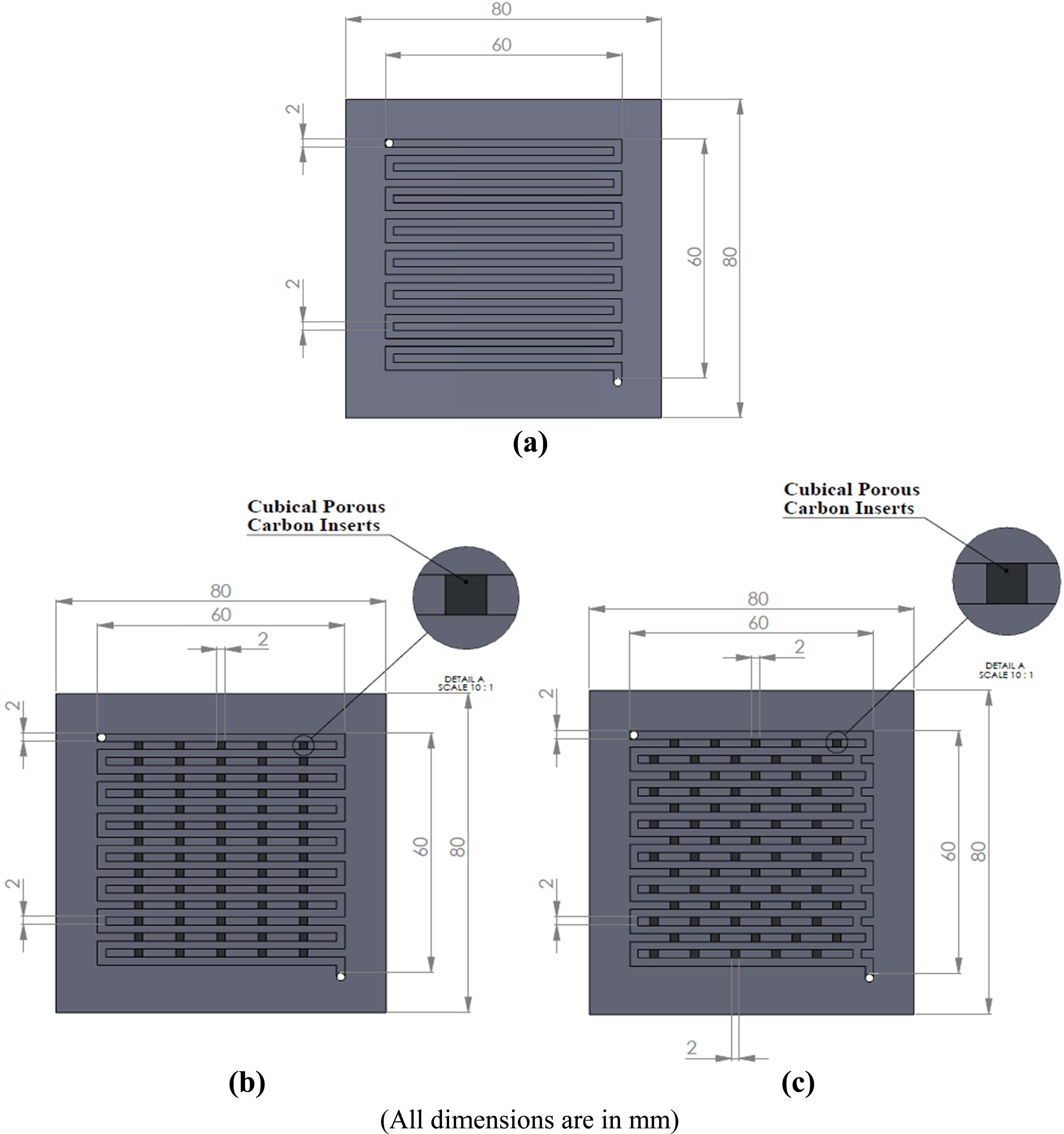
Based on the numerical and experimental investigations from the past works [14, 15] it is concluded that better cell performance is achieved by serpentine flow field due effective water transport within the cell. The serpentine flow field designs are widely used for many applications because of the better cell performance, durability and reliability. Hence, the serpentine flow field has been selected on anode side for all the experimental studies. But on the cathode side, flow field design is modified for better water management as the water flooding is mainly occurring on the cathode side of PEMFC, due to Oxygen Reduction Reactions (ORR). In addition, increasing active area further increases the water formed in the cell due to more electrochemical reactions. So, effective water control is required with the special flow field while scaling up PEMFC. Hence, novel flow fields, namely, the uniform and stagger patterned flow fields with porous inserts have been used on cathode side along with serpentine flow field on anode side. For comparative study of new designs with serpentine flow field design, the following combinations of flow field designs on anode and cathode sides have been used for smaller and larger active areas of PEMFCs. The flow field designs on cathode side for PEMFC with 36 cm2 active area used for experimentations are shown in Fig. 1. The flow field on anode side is serpentine in all three cases as water flooding is less on anode side. Similar arrangements were made for PEMFCs with active area of 25 cm2 and 70 cm2.
|
Fig. 1 Flow field designs of 36 cm2 active area (a) Serpentine (b) Uniform patterned pin type with porous inserts (c) Stagger patterned pin |
The design of the “porous inserts” is based on the two main parameters –Material and Size of porous inserts. Experimental analysis of complete resin-bonded porous flow field shows enhanced performance of PEMFC [26]. The materials considered for their studies have good electrical and thermal conductivities, high porosity high gas permeability and durability. These properties have an impact on the absorption of accumulated water from the GDL and flow field on the cathode side. Even though the power output of complete porous flow field is more than conventional (non-porous) flow field, flow of reactants from the channels across landings of the porous flow field obstructs the performance on the high ranges of ohmic and concentration region. In addition, the machining and assembling of complete porous flow field are the challenging tasks. Hence, the design and development of non-porous uniform and stagger patterned flow field types on the cathode side are used for accommodating porous inserts.
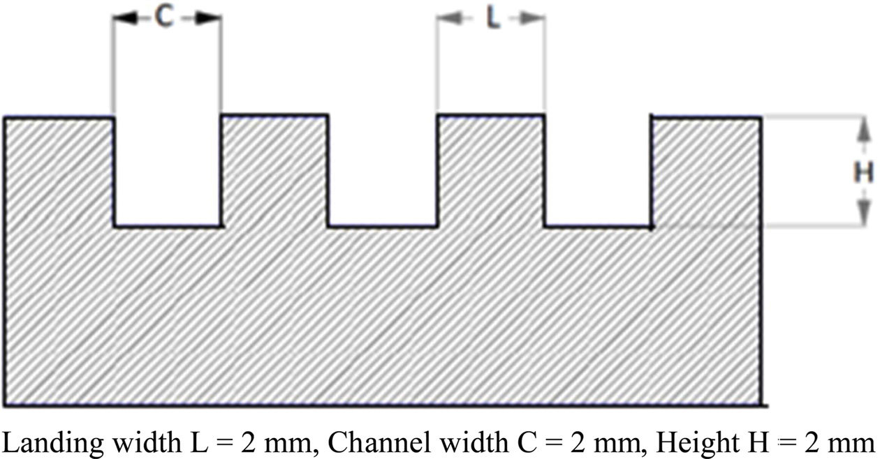
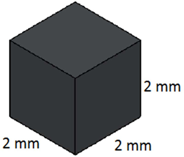
In this paper, the three flow fields (serpentine, uniform and stagger patterned) with a landing width to channel width ratio (L:C) of 2:2 have been used. As the porous inserts are fitted along grooves machined in landing of the flow field of L:C = 2:2, the same size of landing width 2 mm and height 2 mm have been considered for design selection criteria of the porous inserts. The cross-sectional view of flow field plate is depcited in Fig. 2. To avoid the cross flow behavior of pin type flow field, the selected 2 ´ 2 ´ 2 mm3 cubical porous inserts (as shown in Fig. 3) have been fitted along the grooves in the landing of the pin type flow field in uniform and stagger patterns on the cathode side. The flow field design obtained gets the advantages of the serpentine flow field, along with enhanced water management properties due to the provision of porous inserts on the landing of the cathode flow field. Apart from that, right now the fabrication and fixing of porous inserts with the bigger sizes are the challenging tasks. In future, the bigger size of solid porous inserts will be made and their impact on PEMFC performance will be studied.
|
Fig. 2 Cross-sectional view of the flow field on anode and cathode. |
|
Fig. 3 Porous insert. |
The numerical investigation on 25 cm2 PEMFC with the novel cathode flow field design with porous inserts showed the improved performance. Also from the study of the influence of various porosity ranges (60-70%, 70-80% and 80-90%) of the carbon inserts, it is found that the stagger patterned pin type flow field with porous inserts of high porosity range of 80-90% gives high performance on PEMFC.
The Biologic FCT-50S is a computer integrated test station, which is programmed to control the load, pressure, temperature, relative humidity and flow rate of reactants accurately. The data acquisition is attained by use of an Ethernet cable. The fuel cell test station can be used to measure upto 250 W power with current and voltage upto a maximum of 50 A and 5 V respectively. Flow rate of reactant upto 1.5 lpm on anode side and 1.0 lpm on cathode side can be achieved. Hydrogen of 99.99% purity is used as fuel on anode side and medical grade oxygen is used as oxidant on cathode side. Pressure gauges which are in line with the outlet of the reactants are used to measure the pressure in the fuel cell.
Initially, activation is required for properly humidifying the MEA which might be dried out during the hot pressing in the fabrication of the 5 layer MEA. The anode GDL and catalyst layers, membrane, cathode catalyst layer and GDL are the five layers of MEA. The following procedure is developed for activation of MEA based on a number of trials which include constant power, constant current and constant voltage modes by using a looping process. Primarily, a Voltage pulse with 0.6 V constant voltage is maintained for one hour, followed by a looping process, which alternates between 0.7 V and 0.5 V for every 20 minutes until the value of current produced reaches a maximum for the given voltage. Finally, a current pulse with a current density of 200 mA/cm2 is maintained until the stabilization of voltage takes place for all PEMFCs. The activation of MEA guarantees that the MEA can perform at its maximum power density by activating catalyst sites during this process. The studies on scaling up of fuel cells is continued after the activation of MEA.
The porous inserts are the small cubical solid substances/bodies made of Vulcan carbon, which have the properties of good water absorption through their high porous structure along with good electrical and heat conductivities. Porous inserts are prepared by using Vulcan carbon as base material and PolyVinyl Alcohol (PVA) as binder material. Initially, a polymer solution is prepared by dissolving 0.3 g of PVA in 30 ml of distilled water with magnetic stirrer. The polymer solution is then added drop wise to the Vulcan carbon until the mixture reaches a semisolid state. The mixture is then cast into cubical inserts of side 2 mm. The casted carbon inserts are then sintered at 300oC in a furnace for vaporizing the binding polymer PVA. Also, this sintering process improves the structural strength and porosity of the porous inserts by the removal of polymer binder.
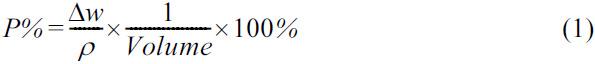
The porosity of porous inserts is found by Liquid absorption method which utilizes a non-reactive liquid such as glycerol to fill up the pores. The difference of initial and final weights of the porous inserts before and after dipping into the glycerol gives the weight of glycerol entered into the pores of the carbon insert. The porosity (P%) can be measured [27] from the change in weight (∆w) of porous inserts, density of glycerol (ρ = 1.261 g/cm3) and volume of porous inserts (8 mm3), by using equation (1).
The porous inserts with 80-90% porosity are used in this investigation, as they yield better performance on PEMFCs [19, 22]. The carbon inserts are placed in the grooves with the help of a tweezers in the landings of uniform and stagger patterned pin type flow fields by using a thin layer of electrically conductive glue which is applied on the bottom face of the porous insert to ensure that they are fixed firmly. The porous inserts will block the passage of the oxygen flow in the cathode flow channels, if they fall off from their corresponding positions. The positioning of porous inserts along the grooves of flow field changes the flow field design from pin type to serpentine type which is essential for improved water management on cathode side of PEMFC.
‘Voltage pulse’ and ‘Current scan’ techniques have been performed among various experiments available in the test station. The voltage pulse steps the potential with reference to absolute potential (E) or initial potential. This is based on estimated current response for potential step applied. The current scan sweeps the applied current to the PEMFC from zero in programmed increments until a set value is finally reached. This gives an estimate of the maximum power density and voltages of the PEMFC.
The three flow fields on cathode side, namely, serpentine, uniform and stagger patterned pin type with porous inserts with active areas 25, 36 and 70 cm2 have been investigated experimentally. All flow field designs have a common Landing width to Channel width ratio (L:C) of 2:2. The 25 cm2 active area PEMFC has been tested at 313 K temperature for cell, humidifier and reactants. The flow rate at anode has been maintained at 550 ml/min and the same for cathode has been maintained at 280 ml/min. Also, the operating pressure of 1 bar has been maintained. The same experimental conditions have been repeated for active areas of 36 and 70 cm2 with different reactant flow rates based on the size of the MEA/cell. The stoichiometries have been maintained at 2.6, 2 and 2.5 for conducting the experiments on 25, 36 and 70 cm2 PEMFCs respectively. After the activation of MEA, the experimental works have been carried out.
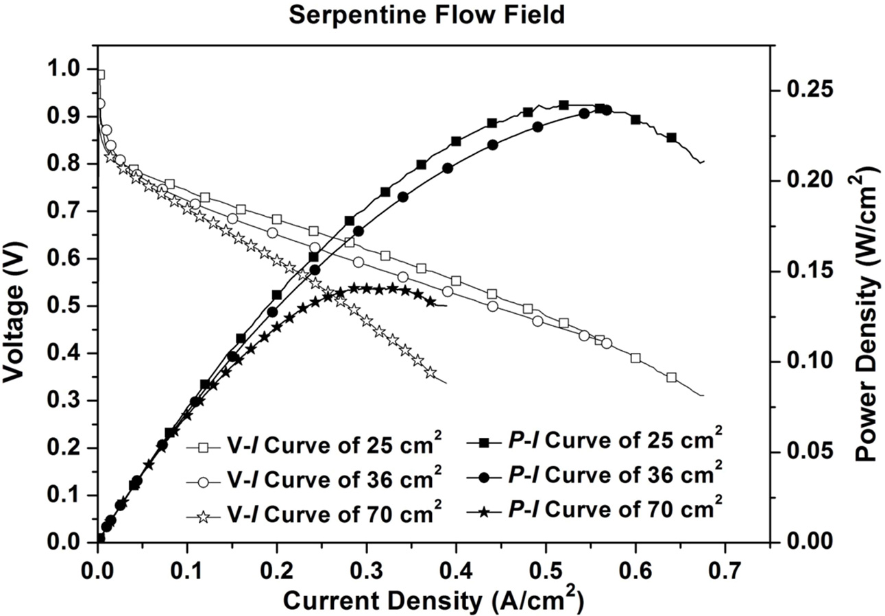
While analyzing the output of PEMFCs having serpentine flow field on cathode side with different active areas of 25, 36 and 70 cm2, the power densities obtained are 0.242 W/cm2, 0.240 W/cm2 and 0.141 W/cm2 respectively and the respective current densities are 0.676 A/cm2, 0.570 A/cm2 and 0.389 A/cm2 respectively. From the above, the PEMFC of 25 cm2 active area with serpentine flow field yields higher power density and current density. This is due to better water management in 25 cm2 compared to other active areas. Fig.4 shows the power density (P-I) and polarization (V-I) curves of the serpentine flow field design of PEMFC with active area of 25 cm2, 36 cm2 and 70 cm2. The length of the flow path in 25 cm2 is shorter than the length of path in 36 cm2 and 70 cm2. So the water formed in cathode flow channel is removed easily by the flow of reactant. In the serpentine flow field, the maximum performance is due to the higher pressure drop that yields diffusion along with forced convection in the transverse direction (Z-direction). Hence the reactants spent more time on catalyst sites. But due to increase in active area of PEMFC, the removal of water is difficult.
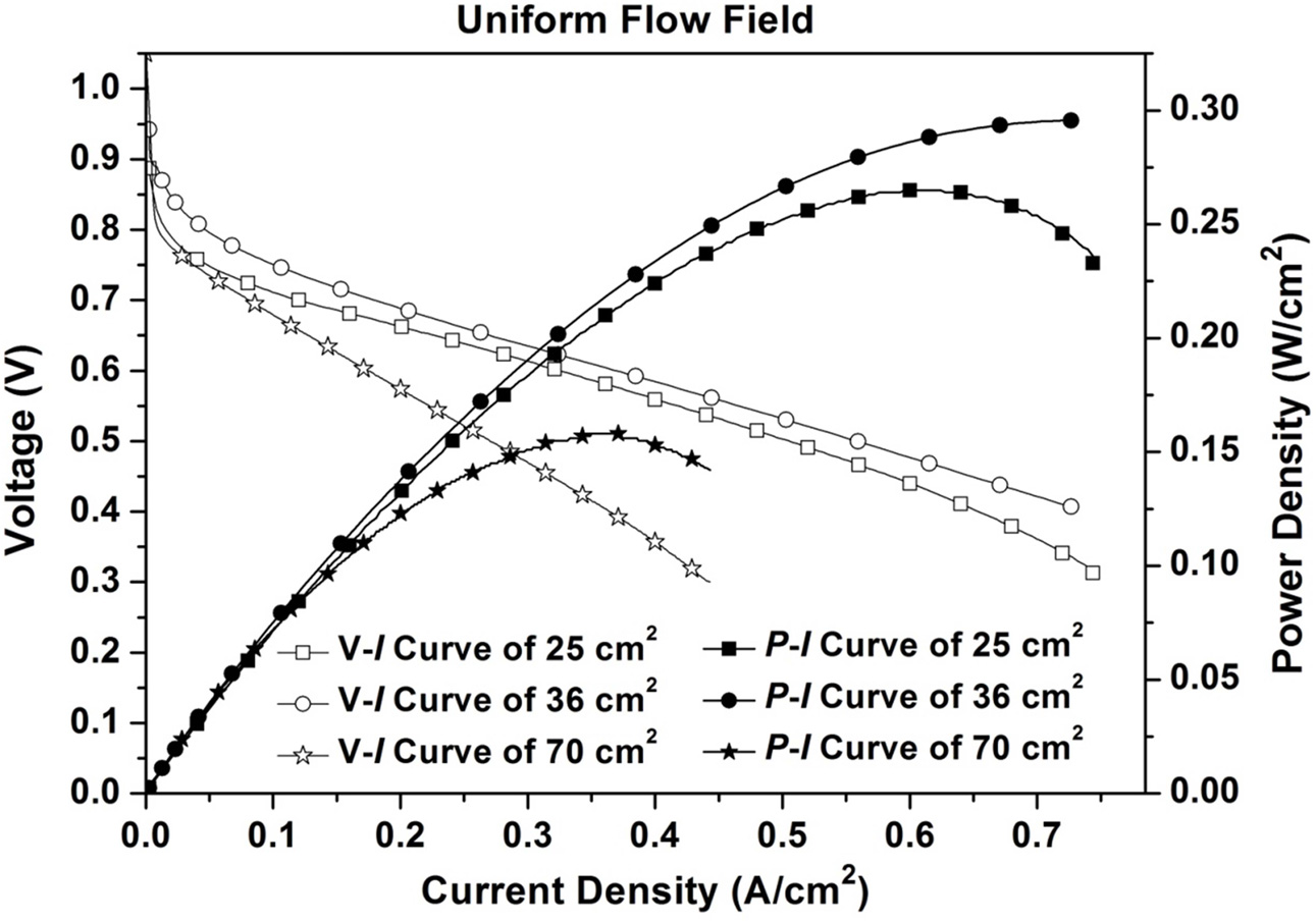
While analyzing the output of PEMFCs with Uniform patterned pin type flow field having porous inserts on cathode side with different active areas of 25 cm2, 36 cm2 and 70 cm2, the power densities obtained are 0.265 W/cm2, 0.295 W/cm2 and 0.158 W/cm2 respectively and the respective current densities are 0.748 A/cm2, 0.732 A/cm2 and 0.427 A/cm2 respectively. From the above, the 36 cm2 PEMFC with uniform patterned pin typeflow field having porous inserts yields a higher power density. Fig. 5 shows the power density (P-I) and polarization (V-I) curves of the uniform patterned pin type flow field design having porous inserts of PEMFC with active area of 25 cm2, 36 cm2 and 70 cm2.
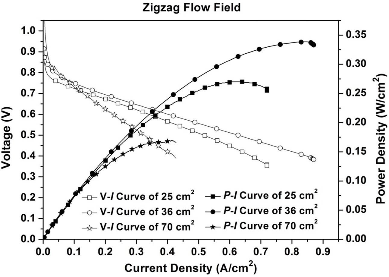
While analyzing the output of PEMFCs with stagger patterned pin type flow field having porous inserts on the cathode side with different active areas of 25 cm2, 36 cm2 and 70 cm2, the power densities obtained are 0.270 W/cm2, 0.338 W/cm2 and 0.170 W/cm2 respectively and the respective current densities are 0.724 A/cm2, 0.871 A/cm2 and 0.423 A/cm2. From the above, the 36 cm2 PEMFC with stagger patterned pin type flow field having porous inserts yields a higher power density. Fig.6 shows the power density (P-I) and polarization (V-I) curves of the stagger patterned flow field design having porous inserts of PEMFC with active area of 25 cm2, 36 cm2 and 70 cm2.
While placing the porous inserts on the landing, the flow field changes from pin type to serpentine. This modified flow field design inherits the benefit of the serpentine type flow field and it has the ability to absorb the water in the landing. PEMFC having stagger patterned pin type flow field with porous inserts gives high performance compared to serpentine flow field and uniform patterned pin type flow field with porous inserts due to better water management.
In uniform patterned pin type flow field design, the arrangement of porous inserts follows an order of linearity or uniformity. However, in stagger patterned pin type flow field design, the porous inserts fixed on the landing surface do not follow any uniformity/ linearity with its adjacent landing surface. But there is uniformity in the arrangement of porous inserts, when an odd or even number of landings are considered. Due to this, the arrangement of porous inserts becomes widespread rather than localized as in the case of uniform patterned pin type design. As a result, in the stagger patterned arrangement, the water absorption at the interfacial region between the membrane and GDL becomes more globalized and the majority of the area gets covered for water absorption, but in uniform pattern arrangement, the localized water absorption is seen. So the performance of Stagger patterned pin type flow field with porous inserts is better than the uniform patterned pin type flow field with porous inserts.
The fixation of porous inserts on the landing surface of the cathode flow field has an influence on performance improvement of PEMFC compared with serpentine flow field. The reason being the porous inserts through the capillarity of its porous structure removes the accumulated liquid water from the landing surface and eliminates the stagnant regions under the landing, thereby reducing water flooding in the interface between landing and GDL surfaces. Once the porous insert reaches its maximum water absorbing capability through the absorption of water from the interfacial region between landing and GDL, it starts to drain out the excess water to the flow channel. This drained water is then carried away to the outlet of flow channel by the gaseous forces of the incoming reactant stream.
|
Fig. 4 Power density (P-I) and polarization (V-I) curves of the serpentine flow field design of PEMFCs with active area of 25 cm2, 36 cm2 and 70 cm2. |
|
Fig. 5 Power density (P-I) and polarization (V-I) curves of the Uniform patterned flow field design with porous inserts of PEMFCs with active area of 25 cm2, 36 cm2 and 70 cm2. |
|
Fig. 6 Power density (P-I) and polarization (V-I) curves of the Stagger patterned flow field design with porous inserts of PEMFCs with active area of 25 cm2, 36 cm2 and 70 cm2. |
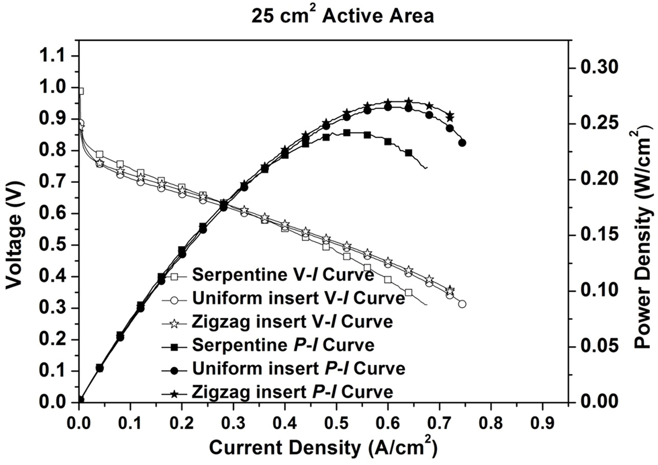
The peak power densities obtained for 25 cm2 PEMFC are 0.242 W/cm2, 0.265 W/cm2 and 0.270 W/cm2 for the serpentine flow field; Uniform and Stagger patterned pin type flow fields with porous inserts respectively, with respective current densities of 0.676 A/cm2, 0.748 A/cm2 and 0.724 A/cm2. While comparing the results of 25 cm2 PEMFC with three different flow field designs, the Stagger patterned pin type flow field with porous inserts result in higher power density. The power density (P-I) and polarization (V-I) curves drawn for the 25 cm2 PEMFCs with three different flow field designs are shown in Fig. 7.
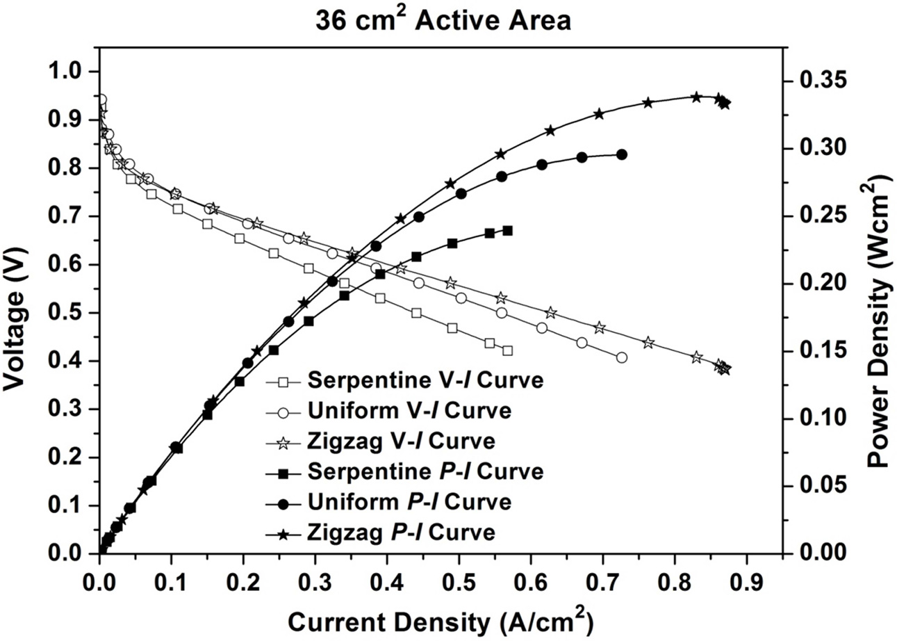
The peak power densities obtained for 36 cm2 PEMFC are 0.240 W/cm2, 0.295 W/cm2 and 0.338 W/cm2 for the serpentine flow field; Uniform and Stagger patterned pin type flow fields with porous inserts respectively, with respective current densities of 0.570 A/cm2, 0.732 A/cm2 and 0.871 A/cm2. While comparing the results of 36 cm2 PEMFC with three different flow field designs, the Stagger patterned pin type flow field with porous inserts results in higher power density. The power density (P-I) and polarization (V-I) curves drawn for the 36 cm2 PEMFC with three different flow field designs are shown in Fig. 8.
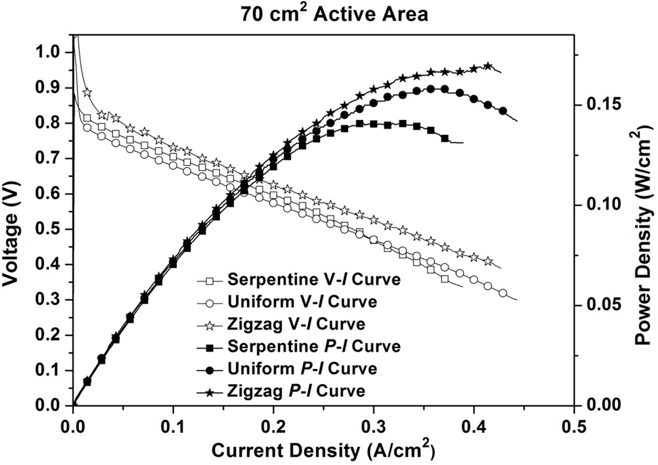
The peak power densities obtained for 70 cm2 PEMFCs are 0.141 W/cm2, 0.158 W/cm2 and 0.170 W/cm2 for the serpentine flow field; Uniform and Stagger patterned pin type flow fields with porous inserts respectively, with respective current densities of 0.389 A/cm2, 0.427 A/cm2 and 0.423 A/cm2. While comparing the results of 70 cm2 PEMFC with three different flow field designs, the Stagger patterned pin type flow fields with porous inserts results in higher power density. The power density (P-I) and polarization (V-I) curves drawn for the 70 cm2 PEMFC with three different flow field designs are shown in Fig. 9.
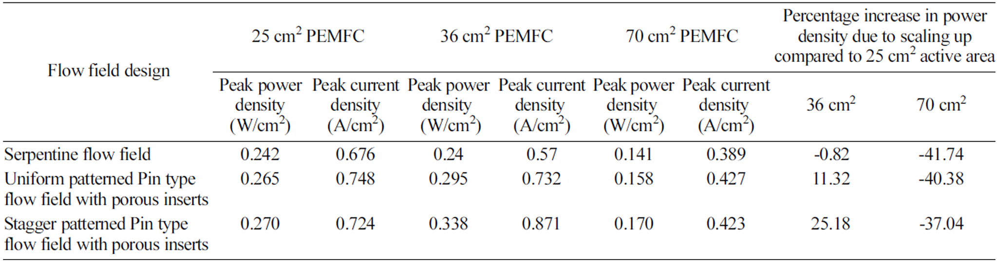
The power and current densities of different flow field designs with different active areas are given in Table 1. While scaling up the area from 25 cm2 to 36 cm2, the power density of PEMFC with serpentine flow field design has dropped by 0.82%. Whereas the scaling up the area from 25 cm2 to 36 cm2, the power densities of PEMFCs with uniform and stagger patterned flow field designs having porous inserts, are increased by 11.32% and 25.18% respectively. While scaling up the area from 25 cm2 to 70 cm2 PEMFCs with serpentine flow field design, the power density has dropped by 41.74%. Whereas the scaling up the area from 25 cm2 to 36 cm2PEMFCs with uniform and stagger patterned flow field designs having porous inserts, the power densities are increased by 11.32% and 25.18% respectively. It is observed that the scaling up of active area from 25 cm2 to 36 cm2 invariantly increases the power density regardless of flow field design while doing the same by further increasing the active area to 70 cm2 results in a decreased power density. This may be due to the tradeoff achieved by 36 cm2 active area between the time available for reaction and the effect of flooding due to scaling up based on the intricate relations existing between the flow of reactants inside the cell and the size of the active area. Also the reduction in the ohmic losses, a reduction in the resistance of the cell components, higher mass transportation in the cell and low production of water inside the cell are the main reasons for the high performance of 36 cm2 active area.
|
Fig. 7 Power density (P-I) and polarization (V-I) curves of 25 cm2 PEMFC with three different flow field designs. |
|
Fig. 8 Power density (P-I) and polarization (V-I) curves of 36 cm2 PEMFC with three different flow field designs. |
|
Fig. 9 Power density (P-I) and polarization (V-I) curves of 70 cm2 PEMFC with three different flow field designs. |
|
Table 1 Power and current densities of different flow fields with different active areas |
The performance studies on scaling up the active area from 25 cm2 to 36 cm2 and 70 cm2 PEMFCs with different flow field designs like serpentine, uniform and stagger patterned pin type flow fields with porous inserts on cathode side have been conducted.
Adopting the porous inserts with the porosity range of 80-90% on uniform and stagger patterned pin type flow field designs, shows the best performance with 9.5% and 11.6% increase in power densities respectively on 25 cm2 PEMFC; 22.9% and 40.8% increase in power densities respectively on 36 cm2 PEMFC; and 12.1% and 20.6% increase in power densities respectively on 70 cm2 PEMFC, when compared to serpentine flow field.
The insertion of porous inserts along the landing of the cathode pin type flow field has a major impact on addressing the flooding effect in scaling up studies on PEMFC performance with better water transport characteristics. With the experimental validation of all the tests, the water flooding can be controlled effectively, that resulted in performance enhancement of PEMFC in scaling up studies.
The current density decreases as the active area is increased in serpentine flow channel since the water flooding reduces the performance of fuel cell. However, usage of porous inserts results in better water management in uniform and stagger patterned flow fields which in turn increase the current density as the active area increase from 25 cm2 to 36 cm2. Conversely, while scaling up from 36 cm2 to 70 cm2, water flooding gains dominance and current density decreases.
When the active area of the PEMFC is increased, the total power output also directly increases with the active area. However, there is a deviation in the power density. The power density is high for the PEMFCs with 36 cm2 active area compared to 25 cm2 and 70 cm2 active areas due to complex relations existing between the flow of reactants on the cell with the size of the active area. The influence of ohmic losses is less in 36 cm2. In addition, the key factors such as ineffective cooling and the water lodging at the cathode are influencing the power drop in scaled up PEMFCs. It is concluded that the active area of 36 cm2 is the optimum size compared to 25 cm2 for the further studies on PEMFCs.
The authors would like to thank Department of Science and Technology, Government of India, New Delhi Project Sanction No: SR/S3/CE/006/2011 for providing the necessary funding and support to carry out this work.
- 1. B.S. Koh, J.H. Yoo, J.H. Kim, and S.C. Yi, J. Ceram. Process. Res. 17 (2016) 332-337.
- 2. S.J. Lee, S. Shin, J.H. Yoo, and S.C. Yi, J. Ceram. Process. Res. 18 (2017) 666-670.
- 3. L. Hui, T. Yanghua, W. Zhenwei, S. Zheng, W. Shaohong, S. Datong, Z. Jianlu, F. Khalid, Z. Jiujun, W. Haijiang, L. Zhongsheng, A. Rami, and M. Antonio, J. Power Sources 178 (2008) 103-117.
-

- 4. M.M. Mench in “Fuel cell engines” (John Wiley 2008) p.298.
-
- 5. F. Barbir, H. Gorgun, and X. Wang, J. Power Sources 141 (2005) 96-101.
-
- 6. D.L. Wood, S.Y. Jung, and T.V.Nguyen, Electrochim. Acta 43 (1998) 3795-3809.
-
- 7. P.M. Belchor, M.M.C. Forte, and D.E.O.S Carpenter, Int. J. Hydrogen Energy 37 (2012) 11904-11911.
-
- 8. N. Bunmark, S. Limtrakul, M. W.Fowler, T. Vatanatham, and J. Gostick, Int. J. Hydrogen Energy 35 (2010) 6887-6896.
-
- 9. A.P. Manso, F.F. Marzo, J. Barranco, X. Garikano, and G.M.Mujika, Int. J. Hydrogen Energy 37 (2012) 15256-15287.
-
- 10. J.P. Owejan, T.A. Trabold, D.L. Jacobson, M. Arif, and S.G. Kandlikar, Int. J. Hydrogen Energy 32 (2007) 4489-4502.
-
- 11. Y.M. Ferng and A. Su, Int. J. Hydrogen Energy 32 (2007) 4466-4476.
-
- 12. S. Shanmugasundaram, R. Gukan, P. Karthikeyan, and R.J. Vasanth, Energy Institute 90 (2017) 363-371
-
- 13. R. Koresawa and Y. Utaka, Int. J. Hydrogen Energy 40 (2015) 8172-8181.
-
- 14. T. Kanezaki, X. Li, and J.J.Baschuk, J. Power Sources 162 (2006) 415-425.
-
- 15. J. Park and X. Li, J. Power Sources 163 (2007) 853-863.
-
- 16. X.D. Wang, Y.Y. Duan, and Yan WM, J. Power Sources 173 (2007) 210-221.
-
- 17. W.M. Yan, H.Y. Li, P.C. Chiu, and X.D. Wang, J. Power Sources 178 (2008) 174-180.
-
- 18. C.R. Buie, J.D.Posner, T. Fabian, S.W. Cha, D. Kim, F.B. Prinz, J.K. Eaton, and J.G. Santiago, J. Power Sources 161 (2006) 191-202.
-
- 19.
P. Karthikeyan, R.J. Vasanth, and M. Muthukumar, Int. J. Hydrogen Energy 40 (2015) 4641-4648. -
- 20. P. Karthikeyan, P. Velmurugan, G.A. Joseph, R. RamKumar, and R.J. Vasanth, Int. J. Hydrogen Energy 39 (2014) 11186-11195.
-
- 21. A. Su, F.B. Weng, C.Y. Hsu, and Y.M. Chen, Int. J. Hydrogen Energy 31 (2006) 1031-1039.
-
- 22. P. Karthikeyan, M. Muthukumar, and R.J. Vasanth, Int. J. Hydrogen Energy 41 (2016) 2867-2874.
-
- 23. P. Karthikeyan, M. Muthukumar, S. Vignesh Shanmugam, P. Pravin Kumar, and S. Murali, A.P. Senthil Kumar, Procedia Engineering 64 (2013) 409-418.
-
- 24. H. Liu, P. Li, and K. Wang, Int. J. Hydrogen energy 38 (2013) 9835-9846.
-
- 25. S.A. Saco, R.T.K. Raj, and P. Karthikeyan, Energy 113 (2016) 558-573.
-
- 26. P. Karthikeyan, L.H. Calvin, G. Lipscomb, S. Neelakrishnan, A.J. George, and R. Anand, in Proceedings of the ASME 2012 International Mechanical Engineering Congress & Exposition (2012) p.781-788.
-
- 27. R.K. Selvan, C.O. Augustin, L.J. Berchmans, and R. Saraswathi, Materials Research Bulletin 38 (2003) 41-54.
-
 This Article
-
2019; 20(5): 490-498
Published on Oct 31, 2019
- 10.36410/jcpr.2019.20.5.490
- Received on Jun 13, 2019
- Revised on Jun 24, 2019
- Accepted on Jun 25, 2019
Services
- Abstract
introduction
selecting the size of active area and
various flow field designsscientific evaluation of insert technology
scientific modeling of the present work
experimental work
results and discussion
conclusions
acknowledgment
- References
- Full Text PDF
Shared
Correspondence to
- P. Karthikeyan
-
Fuel Cell Energy System Laboratory, Department of Automobile Engineering, PSG College of Technology, Coimbatore-641004, India
Tel : +91 422 2572177
Fax: +91 422 2573833 - E-mail: apkarthipsg@gmail.com; apk.auto@psgtech.ac.in
Clean-Energy Research Institute(CRI), Hanyang University, 222, Wangsimni-ro, Seongdong-gu, Seoul, 04763, Korea
E-mail: jcpr@hanyang.ac.kr