


- Electrical characteristics of multi-walled carbon nanotube-polyethylene composites by catalyst and gas control
Suyoung Parka, Sun-Woo Choib,* and Changhyun Jinc,d,*
aDepartment of Aviation Maintenance Engineering, Far East University, Chungbuk 27601, Korea
bDepartment of Materials and Metallurgical Engineering, Kangwon National University, Samcheok 25913, Korea
cDivision of Materials Science and Engineering, Hanyang University, Seoul 04763, Korea
dThe Research Institute of Industrial Science, Hanyang University, Seoul 04763, Korea
In this study, the electrical conductivity of multi-walled carbon nanotubes (MWCNTs) and polyethylene synthesized by an extrusion process was evaluated. The MWCNTs used exhibited differences in their dispersion characteristics depending on the type of catalyst or synthesis gas used. Thus, the choice of catalyst or synthesis gas significantly affect the physicochemical state of the final MWCNTs and MWCNT-based composites. In this investigation, the characteristics of MWCNTs were analyzed in four cases by introducing ethylene and propylene gas to each catalyst synthesized using deposition precipitation and spray drying methods. The MWCNT-based composites synthesized using the catalyst prepared by deposition precipitation and the ethylene synthesis gas showed the best electrical conductivity. In principle, the morphologies of the MWCNTs indicate that the smaller the aggregate size and bundle thickness, the better the electrical conductivity of the MWCNT composites. This implies that the network is well-formed.
Keywords: MWCNT, Polyethylene, Deposition precipitation, Spray drying, Electrical conductivity
After the discovery of carbon nanotubes (CNTs) by Dr. Ijima of Japan [1] , these nano-materials have been intensively investigated [2-6]. For example, given that CNTs are considered to be a high-tech material and an example of a nano-material, they also exhibit superior electrical, mechanical and chemical properties and specific surface area, compared to carbon fiber and carbon black. As such, they are receiving much attention in basic research fields and industrial applications [7-9]. In addition, there is currently active research on the manufacture and dispersion of nanocomposites with CNTs that can realize various functions including high strength, electric conductivity, electrostatic radiation properties, and abrasion resistance [10-11]. In addition, the excellent electrical conductivity properties of CNTs can be manifested in polymer nanocomposites by mixing with a polymer matrix to yield new properties that are difficult to realize in polymers [12-13]. However, since CNTs are agglomerated by the surface attraction force, that is, van der Waals forces act on the CNTs, the binding force of CNTs is low and they do not exhibit excellent properties [14-16]. Therefore, the CNT dispersion problem is a major challenge in the study of nanocomposites [17-19].
Among the various CNT dispersion methods, physical dispersion using a high shear force is well-known [20]. Polypropylene (PP) and polyethylene (PE) are among the major polymers used in composite materials and have excellent heat resistance and are light weight. Moreover, they have excellent tensile strength, which are desirable mechanical properties [21-23]. In addition, CNT-based composites have been used in semiconductor processing, particularly in cleaning processes and etching to remove contamination on carriers and wafer surfaces, and they play a significant role in automation systems [24-26].
In this research, the electrical properties of MWCNT-polymer composites were measured through optimization of MWCNT synthetic gas. Two different methods of MWCNT were obtained using deposition precipitation (DP) and spray drying (SD) methods, respectively, to obtain MWCNT/PE composites, containing 2 wt% of MWCNT. Therefore, the purpose of this study is to determine the overall characteristics of the sample, not the partial approach, by measuring the electrical properties of each MWCNT-based composite made from different catalysts and different synthetic gases. Thus, using a pellet for the extrusion test, a sheet of a MWCNT/PE composite was prepared by hot pressing, and the validity of each sheet was confirmed.
MWCNTs were synthesized using ethylene gas and propylene gas and were prepared using the deposition precipitation (DP) and spray drying (SD) methods. The DP method catalyst was prepared by using 1 um of aluminum hydroxide as a support. A mass of 250.2 g of Iron (III) nitrate nonahydrate (FeN) and 75.5 g of cobalt (II) nitrate hexahydrate (CoN) were dissolved in 1 liter of deionized (DI) using a magnetic stirrer for 20 min. A mass of 1 kg of aluminum hydroxide was added to 2 L of DI water in a large beaker and mixed together. The mixed solution was filtered using a vacuum filtering device. After separation of the catalyst prepared in the silver foil, it was dried in a box type oven at 150 ℃ for 16 hours or more. The catalyst was added and pulverized in a mixer of 300 cc. A total of 1,000 g of Iron(III) nitrate nonahydrate [Fe(NO3)3·9H2O, FeN], 250 g of Cobalt(II) nitrate hexahydrate [Co(NO3)2· 6H2O, CoN], 1,200 g of Aluminum nitrate nonahydrate [Al(NO3)3·6H2O, AlN], and 5 L of DI water were used for the SD catalyst. Thereafter, it was dissolved using a mechanical stirrer for 60 min. The spray drying synthesis furnace was always maintained at 800 ℃. Thus, the spherical size of the catalyst was approximately 1 um. MWCNTs were synthesized by introducing 0.4 g of DP and/or SD catalyst into a boat in a CVD type synthesizer and injecting ethylene and/or propylene synthetic gas at 700 ℃ for 30 min. The morphologies of the synthesized MWCNTs were observed using a scanning electron microscope and transmission electron microscope. MWCNT/PE sheets was fabricated by hot press for 2 min and cooling for 2 min processes after fabrication of composite pellet of 100 g using a twin extruder operating at 200 rpm at 120℃-150℃. The surface electrical resistance of the MWCNT/PE sheet (10 cm × 10 cm) was measured using the 4-probe surface resistance measuring device at each point.
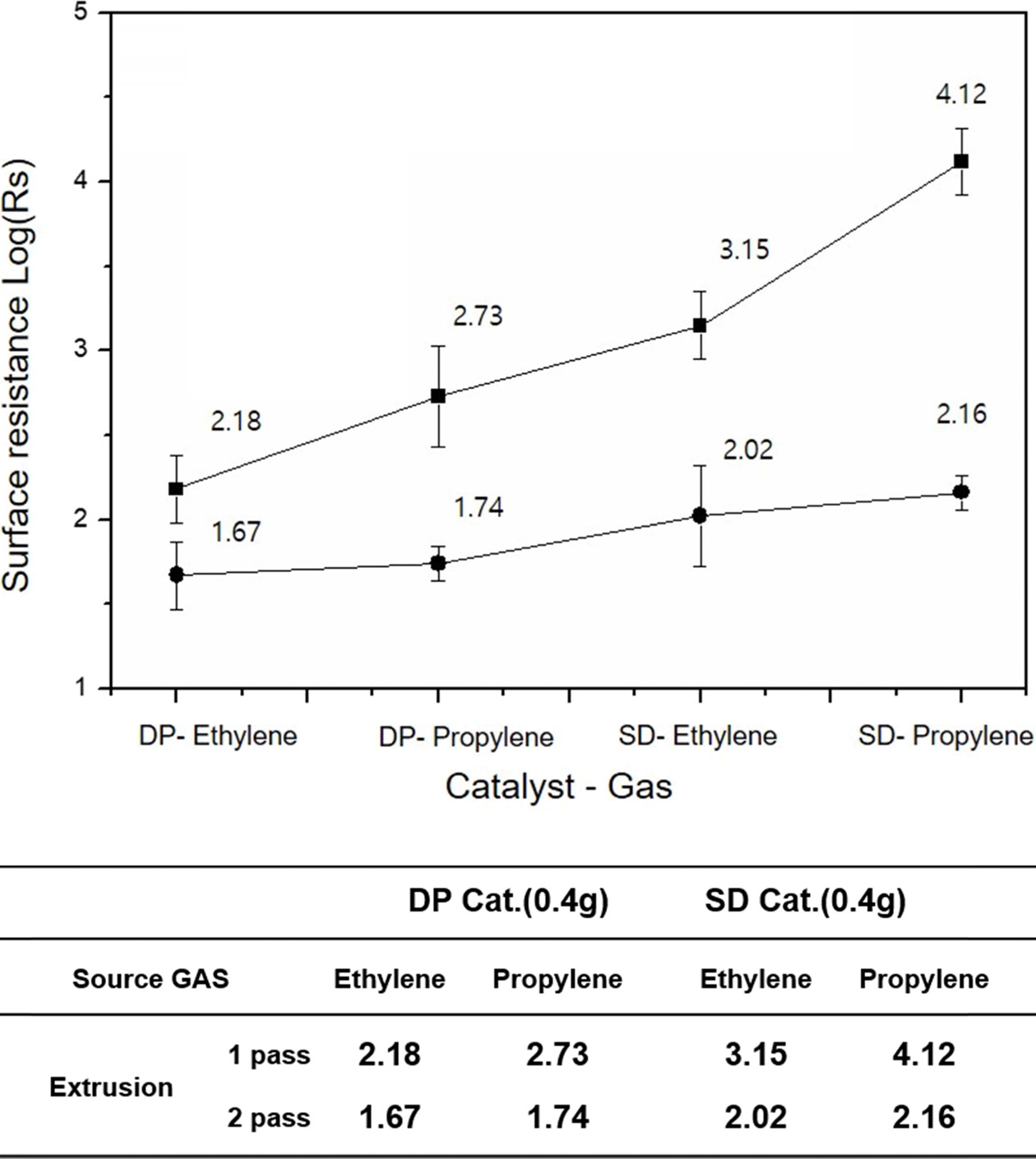
The surface resistivity of the MWCNT/PE composite is shown in Fig. 1 using MWCNT prepared by changing the type of catalyst and synthetic gas. The catalysts used for the synthesis of the MWCNTs were prepared by the DP and SD methods, and ethylene and propylene gas were utilized as synthesis gas. After the synthesis process, the surface resistance of the final MWCNT/PE sheet was measured. The measured surface resistivity of the MWCNT/PE composites obtained using ethylene gas revealed electrical conductivity compared to the MWCNT/PE obtained using propylene gas. For the electrical conductivity measurements, the extrusion process of MWCNT/PE was measured in one-pass and two-pass (in table of Fig. 1). In this process, since the pass of the extruder increased the mechanical (physical) dispersing effect of the MWCNTs [27-28], this dispersion process is not a choice but a necessary process. The surface resistance values obtained in the one-pass extrusion process were the best when the DP catalyst and ethylene gas were used. That is, samples of MWCNT/PE composites prepared using MWCNT synthesized with DP catalyst and ethylene synthesis gas exhibited excellent electrical conductivity, followed by DP catalyst-propylene, SD catalyst-ethylene, and SD catalyst-propylene in that order. However, the surface resistivity of the MWCNT/PE composite with enhanced mechanical dispersibility after a two-pass extrusion process showed no difference between ethylene and propylene when DP catalyst was used, and there was no difference in the gas type when the SD catalyst was used. This is probably because the MWCNT/PE were well suited to the formation of the CNT network in the composites due to the mechanical dispersing effect by the two-extrusion process only. In addition, the surface resistance value shows a difference when the catalytic method is different. As a result, it was determined that the MWCNT/PE composite made using the DP catalyst method had a better electrical conductivity compared to the composite made using the SD catalyst method. In addition, when ethylene gas was used, both the DP catalyst method and the SD catalyst method revealed that the electro-conductivity was superior to that of propylene gas.
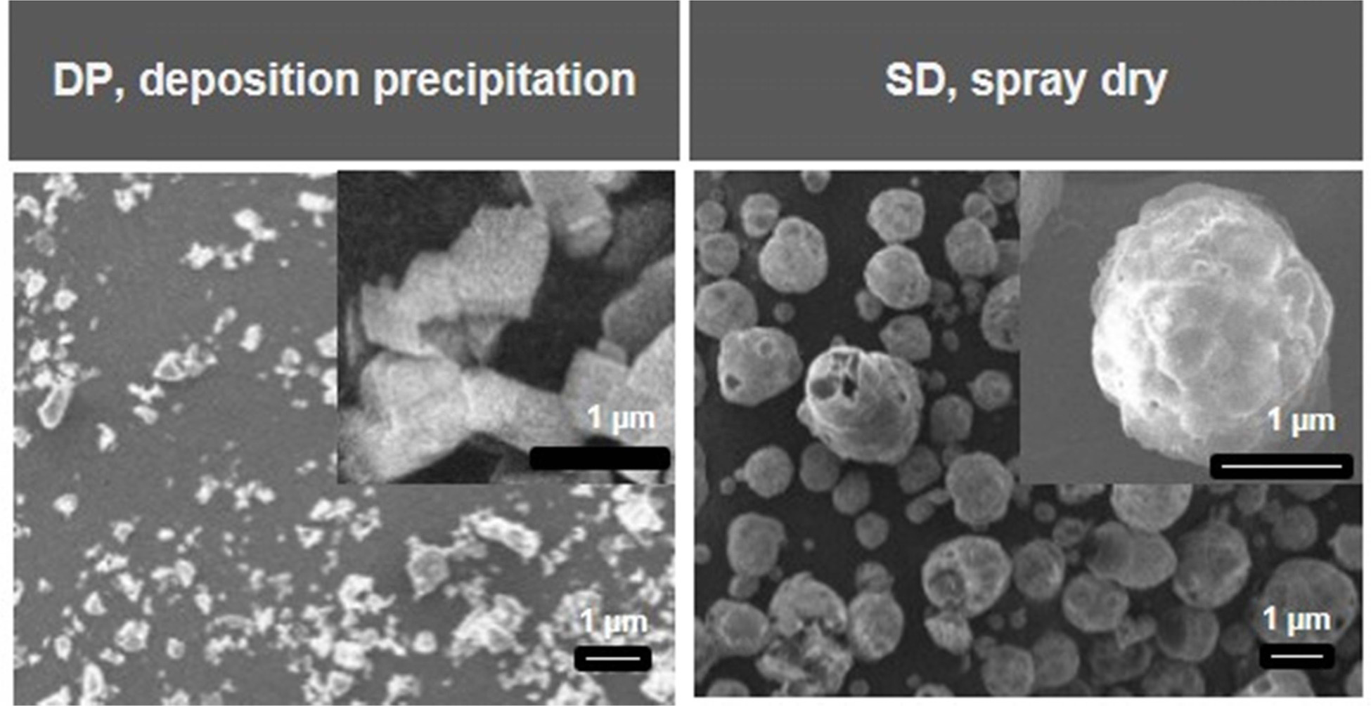
Fig. 2 shows SEM images of the DP and SD catalyst. Fig. 2(a) indicates that the support of the DP method is a seed in which the MWCNTs can grow via the deposition of metal salt with aluminum hydroxide powder. The main components of the catalyst precursor are FeN and CoN and the size of the support is approximately 8 μm for DP catalyst. Currently, MWCNTs grow in various shapes based on the deposition components on the support. Fig. 2(b) is represents a spherical-shaped SD catalyst with a diameter of approximately 1 um prepared by spraying two fluids of catalyst precursor and air together in a drying furnace. A spherical shape is produced as an empty space. Due to the catalyst production characteristics, the SD method tends to grow MWCNT lengths and bundles in all directions as the catalyst space is broken. Therefore, the morphology of the MWCNTs synthesized by the SD catalytic method was longer than that of the MWCNTs synthesized using the catalytic DP method, and the thickness of the bundle was relatively thick.
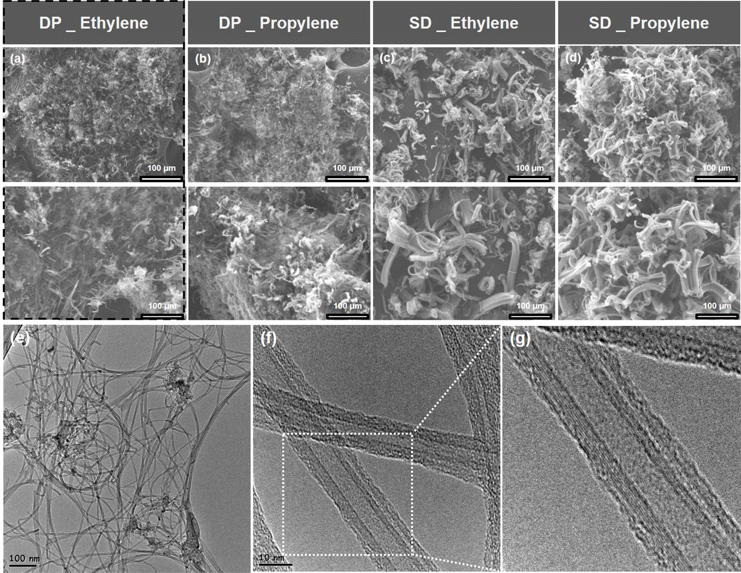
MWCNT synthesized using the DP catalyst method (Figs. 3(a) and 3(b)) and SD catalyst method (Figs. 3(c) and 3(d)) were examined using SEM imaging. Overall, the aggregate size of the MWCNT bundle is small and widely distributed. The bundle length of the MWCNT is approximately 30-40 μm, and the diameter of the aggregate is 50-60 μm. However, the bundle of MWCNTs synthesized using the SD catalyst method exhibited a straight alignment and the bundle length of the MWCNT is approximately 50-60 μm. The diameter of the MWCNT aggregate and the length of the bundle are two of the major factors that affect the dispersibility of MWCNTs. However, MWCNTs are difficult to disperse because the van der Waals forces between their bundles acts in all the directions of the aggregate. Figs. 3(e)-3(f) show typical TEM images under the DP catalyst-ethylene gas conditions with the best dispersion and best electrical properties. From low magnification (Fig. 3e) to high-resolution TEM (HRTEM) (Fig. 3g), it was confirmed that samples were MWCNTs composed of multiple layers rather than one layer.
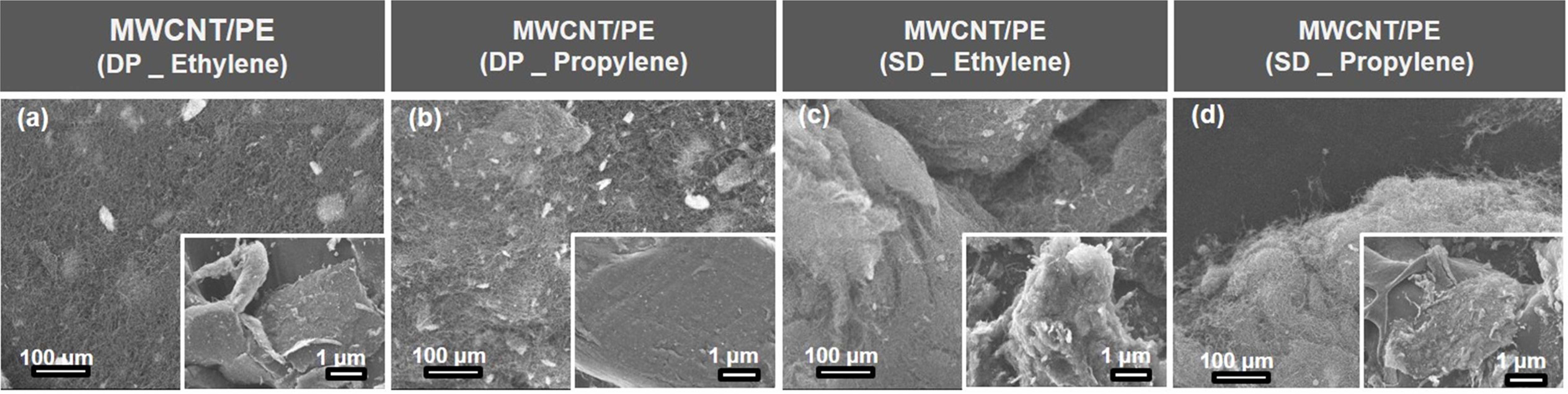
Fig. 4 indicates the degree of dispersion in the MWCNT/PE composite made through extrusion and hot press processes, with heat treatment at 450 ℃ for 10 min in a furnace. In the ethylene gas atmosphere, the DP-based MWCNT image (Figs. 4a and 4b) indicates more uniform distribution compared to the SD-based MWCNT image (Figs. 4c and 4d), and the DP-based MWCNTs are less aggregated. Thus, the electrical conductivity of the DP composite is better. The SEM images presented in Figs. 4c and 4d show the dispersed morphology of the MWCNT/PE composites synthesized using SD catalyst-ethylene gas and SD catalyst-propylene gas, respectively. It can be seen that a large number of MWCNT/PE bundles are formed in the SEM image. This aggregate phenomenon is one of the reasons why the MWCNT network is not well-formed in the composite, which hinders the electrical conductivity.
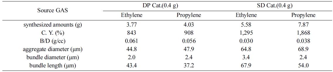
Table 1 summarizes the dimensions and extrusion evaluation of the samples synthesized using ethylene and propylene gas processes, on a catalyst made using DP and SD catalyst methods. In the case of DP catalyst, 0.4 g of catalyst was added to ethylene and propylene gases, respectively, and the amount of MWCNT synthesized were 3.77 g and 4.03 g, respectively. However, in the case of the SD catalyst, 0.4 g of catalyst was injected into the ethylene and propylene gases, respectively, and the amount of MWCNT synthesized were 5.58 (g) and 7.87 (g), respectively. The amount of MWCNT synthesized via the SD catalyst method was higher than that synthesized by DP catalyst method. This is because the catalyst prepared by the SD method has a hollow spherical form and the MWCNT have a reduced capacity to grow into nanotubes compared to the DP method. The MWCNT conversion value was calculated based on the catalyst added to the synthesis. The yield of MWCNT synthesized by the SD method was higher than that of MWCNT synthesized by DP method catalyst. The amount of carbon-yield is calculated by subtracting the amount of catalyst added and dividing the total amount by the amount of catalyst. This is used as a factor to evaluate the influence of the unreacted catalyst in the MWCNT synthesis process. Since the B/D (i.e., bulk/density) of the MWCNTs is remarkably small, it is inconvenient to handle the work material. As a result, MWCNTs with a B/D value of 0.05 ~ 0.06 (g/cc) obtained by utilizing the DP catalyst method and ethylene synthesis gas, are suitable for collection, storage, movement and extrusion, etc.
Based on the result of the diameter and length of the aggregates and bundles of the MWCNT shown in Table 1, the smaller the diameter of the aggregates, the smaller the surface resistance value obtained. This is because the larger the aggregate, the higher the energy required to disperse the aggregate. The smaller the diameter of the bundle, the better the electrical conductivity. This means that the energy required for dispersion by the van der Waals forces acting between the CNT bundles is small and the smaller the diameter, the less energy required for dispersion. However, the length of the MWCNT bundle was determined to be ideal with respect to the electrical conductivity of the composites of MWCNTs using the DP catalyst and ethylene synthesis gas, and it was not the shortest sample in terms of the MWCNT bundle length. The length of the CNT bundle is determined to be dispersed to form the most appropriate network at a suitable level of approximately 40 to 45 μm in length. If the length of the MWCNT bundle is too long or short, it is difficult for the MWCNTs to form a network within the polymer. In the one-pass extrusion evaluation test, it was confirmed that the composite using the DP catalyst and the MWCNT synthesized using ethylene gas had the best electrical conductivity based on the extrusion evaluation. It was confirmed that the MWCNT aggregate diameter, bundle diameter, and bundle length were correlated with each other, as can be concluded based on the MWCNT morphological analysis described above. However, when the extrusion is performed twice in succession (two-pass), the surface resistance of the sheet indicates that the deviation is smaller in the four samples.
As described above, the ethylene and propylene gases are the main factors that determine the morphological characteristics of carbon, according to the difference of the carbon binding force at the synthesis temperature. Among them, MWCNT/PE synthesized by the DP catalyst-ethylene gas pair showed the best dispersibility.
|
Fig. 1 The electrical resistance values measured on four different MWCNT-based composites synthesized using two different catalysts and gases after one-pass (black color) and two-pass (red color) extrusion. |
|
Fig. 2 Size, shape and distribution according to the type of catalyst. The catalyst synthesized by the SD method has a spherical shape compared to the catalyst synthesized by the DP method. |
|
Fig. 3 Typical SEM and TEM images of MWCNTs formed by two different catalysts and gases. (a-d) SEM images of MWCNTs with (a) DP-Ethylene, (b) DP-Propylene, (c) SD-Ethylene, (d) SD-Propylene, (e-g) TEM images of MWCNTs with DP-Ethylene, (e) low-magnified MWCNTs image, (f) high-magnified MWCNTs image, (g) HRTEM image of MWCNTs. |
|
Fig. 4 Typical SEM images of the MWCNT/PE composites at each condition after completion of catalyst, gas, extrusion, and heat treatment processes. |
In this study, MWCNT/PE composites were prepared by applying different catalysts and different synthesis gases to MWCNTs. The surface conductivities of the MWCNTs and the polyethylene synthesized with DP catalyst - ethylene showed the best electrical conductivity. In addition, the electrical conductivity decreased in the order of DP catalyst-propylene, SD catalyst-ethylene, and SD catalyst-propylene. In addition, MWCNT synthesized via the DP catalyst method showed better dispersibility than MWCNT synthesized by SD catalyst method. The MWCNT/PE sample formed in small MWCNT aggregates and bundle thicknesses. In particular, the bundle length of approximately 45 μm showed excellent electric properties.
This research was supported by Basic Science Research Program through the National Research Foundation of Korea (NRF) funded by the Ministry of Education (NRF-2017R1A6A3A11030900 and 2016R1A6A1A03013422).
- 1. S. Ijima, Nature 354 (1991) 56-58.
- 2. A. Samakande, P.C. Hartmann, V. Cloete, and R.D. Sanderson, Polymer 48 (2007) 1490-1499.
-

- 3. R. J. Chen, Y. Zhang, D. Wang, and H. Dai, J. Am. Chem. Soc. 123 (2001) 3838-3839.
-
- 4. M. Castro, B. Kumar, J.F. Feller, Z. Haddi, A. Amari, and B. Bouchikhi, Sens. Actuators, B 159 (2011) 213-219.
-
- 5. C. Robert, J.F. Feller, and M. Castro, ACS Appl. Mater. Interfaces 4 (2012) 3508-3516.
-
- 6. W. Bauhofer, and J.Z. Kovacs, Compos. Sci. Technol. 69 (2009) 1486-1498.
-
- 7. X. He, F. Zhang, R. Wang, and W. Liu, Carbon 45 (2007) 2559-2563.
-
- 8. T. Saito, K. Matsushige, and K. Tanaka, Phys. B 323 (2002) 280-283.
-
- 9. J.P. Lu, J. Phys. Chem. Solids 58 (1997) 1649-1652.
-
- 10. V. Puchy, P. Hvizdos, J. Dusza, F. Kovac, F. Inam, and M.J. Reece, Ceram. Int. 39 (2013) 5821-5826.
-
- 11. J.A. Kim, D. G. Seong, T.J. Kang, and J.R. Youn, Carbon 44 (2006) 1898-1905.
-
- 12. P. Potschke, M. Abdel-Goad, I, Alig, S. Dudkim, and D. Lellinger, Polymer 45 (2004) 8863-8870.
-
- 13. Y.K. Lee, S.H. Jang, M.S. Kim, H.G. Yoon, S.D. Park, S.T. Kim, and J.D. Lee, Macromol. Res. 18 (2010) 241-246.
- 14. K. Liao, and S. Li, Appl. Phys. Lett. 79 (2001) 4225-4227.
-
- 15. H. Tan, L.Y. Jiang, Y. Huang, B. Liu, and K.C. Hwang, Compos. Sci. Technol. 67 (2007) 2941-2946.
-
- 16. Y. Geng, M. Y. Liu, J. Li, X. M. Shi, and J.K. Kim, Compos. Part A 39 (2008) 1876-1883.
-
- 17. P.C. Ma, N. A. Siddiqui, G. Marom, and J.K. Kim, Compos. Part A 41 (2010) 1345-1367.
-
- 18. Y.S. Song, and J. R. Youn, Carbon 43 (2005) 1378-1385.
-
- 19. F. Inam, A. Heaton, P. Brown, T. Peijs, and M. J. Reece, Ceram. Int. 40 (2014) 511-516.
-
- 20. G. Broza, Comp. Sci. Tech. 70 (2010) 1006-1010.
-
- 21. J.M. Garcés, D.J. Moll, J. Bicerano, R. Fibiger, and D.G. McLeod, Adv. Mater. 12 (2000) 1835-1839.
-
- 22. D. Singla, K. Amulya, and Q. Murtaza, Mater. Today 2 (2015) 2886-2895.
-
- 23. F. Rezaei, R. Yunus, and N.A. Ibrahim, Mater. Des. 30 (2009) 260-263.
-
- 24. S.S. Chougule, and S.K. Sahu, J. Nanotechnol. Eng. Med 5[1] (2014) 010901.
-
- 25. S.A. Gordeyev, J.A. Ferreira, C.A. Bernando and I.M. Ward, Mater. Lett. 51 (2001) 32-36.
-
- 26. D.S Jeong, and B.U. Nam, Polymer (Korea) 35 (2001) 17-22.
- 27. M.T. Müller, B. Krause, B. Kretzschmar, and P. Pötschke, Compos. Sci. Tech. 71 (2011) 1535-1542.
-
- 28. R. Pérez-Bustamante, I. Estrada-Guel, P. Amézaga-Madrid, M. Miki-Yoshida, J.M. Herrera-Ramírez, and R. Martínez-Sánchez, J. Alloys Compd. 495[2] (2010) 399-402.
-
 This Article
-
2019; 20(5): 464-469
Published on Oct 31, 2019
- 10.36410/jcpr.2019.20.5.464
- Received on Mar 1, 2019
- Revised on Jul 12, 2019
- Accepted on Jul 12, 2019
Services
- Abstract
introduction
experimental
results and discussion
conclusions
- Acknowledgements
- References
- Full Text PDF
Shared
Correspondence to
- Sun-Woo Choib , Changhyun Jinc,d
-
bDepartment of Materials and Metallurgical Engineering, Kangwon National University, Samcheok 25913, Korea
cDivision of Materials Science and Engineering, Hanyang University, Seoul 04763, Korea
dThe Research Institute of Industrial Science, Hanyang University, Seoul 04763, Korea
Tel : +82 33 570 6412 and +82 2 2220 0382
Fax: +82 33 570 6419 and +82 2 2220 0389 - E-mail: csw0427@kangwon.ac.kr , chjin0910@gmail.com
Clean-Energy Research Institute(CRI), Hanyang University, 222, Wangsimni-ro, Seongdong-gu, Seoul, 04763, Korea
E-mail: jcpr@hanyang.ac.kr