


- Effect of post-annealing on single-walled carbon nanotubes synthesized by arc-discharge
Suyoung Parka, Sun-Woo Choib,* and Changhyun Jinc,d,*
aDepartment of Aviation Maintenance Engineering, Far East University, Chungbuk 27601, Republic of Korea
bDepartment of Materials Science and Engineering, Kangwon National University, Samcheok 25913, Republic of Korea
cDivision of Materials Science and Engineering, Hanyang University, Seoul 04763, Republic of Korea
dThe Research Institute of Industrial Science, Hanyang University, Seoul 04763, Republic of Korea
In this study, high-purity single-walled carbon nanotubes (SWCNTs) were prepared by removing the unreacted metal constituents and amorphous carbon impurities using a post-annealing process. Unlike conventional thermal processing techniques, this technique involved different gas atmospheres for efficient removal of impurities. A heat treatment was conducted in the presence of chlorine, oxygen, and chlorine + oxygen gases. The nanotubes demonstrated the best characteristics, when the heat treatment was conducted in the presence of a mixture of chlorine and oxygen gases. The scanning electron microscopy, transmission electron microscopy, ultraviolet absorbance, and sheet resistance measurements showed that the heat treatment process efficiently removed the unreacted metal and amorphous carbon impurities from the as-synthesized SWCNTs. The high-purity SWCNTs exhibited improved electrical conductivities. Such high-purity SWCNTs can be used in various carbon composites for improving the sensitivity of gas sensors.
Keywords: Single-walled carbon nanotubes, Heat treatment, Purity, Electrical conductivity
Owing to their high electrical conductivities, thermal conductivities, specific surface areas, and chemical stabilities, carbon nanotubes (CNTs) are extensively used in various applications, such as sensors, nano-composites, and transparent electrodes [1-3]. Over the past few years, there have been several attempts to develop functional materials using single-walled CNTs (SWCNTs) [4]. One of the most popular functional materials includes the field emission displays, which use SWCNTs as the electron emission source. These displays exhibit excellent electrical characteristics and are light-weight [5-8]. However, to develop nanomaterials using CNTs, it is imperative to improve the dispersibility and manipulate the size of the CNTs [9-11]. Typical CNTs possess a diameter of several tens of nanometers and a length of several hundreds of micrometers. CNTs show large aspect ratios and exist in different forms, such as SWCNTs, multi-walled CNTs, and carbon bundles [12, 13]. In addition, the electrical conductance (conductor or semiconductor) and energy gaps of CNTs depend on their stacked forms and diameters, respectively [14, 17]. Therefore, they can undergo conductor-to-semiconductor transitions. However, controlling the electrical conductance of CNTs is difficult. Though different methods are employed for the synthesis of CNTs, the most widely used ones are laser vaporization and arc-discharge [18, 22]. The laser vaporization method was first used for the synthesis of CNTs by Smalley et al. at Rice University [22, 23]. In this method, a graphite target is vaporized in an oven using laser irradiation. The uniformity of the SWCNTs obtained by this method can be improved using graphite targets mixed with metal catalysts, such as cobalt, nickel, and iron. However, as this method produces a low yield of CNTs, it is not suitable for their mass production [24-26]. In the arc-discharge method, the substrate is fixed in a chamber, and a CNT film is directly deposited on the substrate (during the CNT synthesis). Hence, with this approach, CNT films can be produced without employing any additional dispersion or coating processes [27, 28]. CNTs can also be synthesized using the thermal chemical vapor deposition (CVD), plasma enhanced CVD, and vapor phase growth methods [29-31].
In this study, we used the arc-discharge method to fabricate the SWCNTs. Usually, some amorphous carbon and metal residues remain in SWCNTs during their synthesis. These remnants degrade the properties of SWCNTs [32, 33]. Therefore, we employed a heat treatment process to remove these impurities [34, 35]. The optimum heat treatment conditions were also determined. The ultraviolet (UV) absorbance and sheet resistance of the as-synthesized SWCNTs were measured [36, 37]. The findings of this study are effective in developing the CNT composites for various applications [38, 39].
In this study, a metal/metal oxide catalyst, such as Fe/Co/Ni/S/carbon powder, was used. The catalyst material was well-laminated on a carbon rod. The use of metal/metal oxide catalyst materials requires careful consideration, because it can result in the generation of carbon and sulfur compounds during the synthesis. A carbon rod was used as the carbon source for the SWCNT synthesis, and helium gas was used for plasma formation. The equipment was pressurized at 150 Torr and maintained at a current of 400 A. The synthesis time of the SWCNTs was approximately 10 min (the exhaustion period of the carbon rod). The synthesized SWCNTs were then subjected to a heat treatment process, which was conducted in different environments. Chlorine and argon gases were used along with air to remove the impurities of the as-synthesized SWCNTs, while nitrogen gas was used as the purge gas. CO and CO2 gases (from air) were generated during the heat treatment. Therefore, a scrubber treatment was required. The heat treatment of the SWCNTs was conducted at 900 ℃ in an argon gas atmosphere. The furnace temperature was increased at the rate of 15 ℃/min. Then, the SWCNTs were exposed to chlorine, oxygen, and chlorine + oxygen gases at 900 ℃ for 60 min. Then the cooling process was conducted for 120 min, which was completed by introducing argon and nitrogen gases into the furnace. The weights of the samples were measured before and after the heat treatment process.
A UV solution (model 144AX-220, manufacturer Jelight) was prepared for performing the UV measurements. Three different gases, including chlorine, oxygen, and oxygen + chlorine gases were used as the heat-treatment gases. The as-prepared SWCNTs (100 g) and 123 mg of the surfactant were mixed and centrifuged to obtain a solution (143 mg of supernatant and 90 mg of precipitate). The solution was centrifuged at 14,000 rpm for 10 min. This UV solution was dropped on an SEM holder and dried. The lengths of the SWCNTs were observed using an SEM (between the bottom surface and crack opening). The sheet resistance values of the SWCNTs were measured using a four-probe sheet resistance meter. A standard solution of the SWCNT dispersion was coated on a glass plate for conducting the observations. This standard solution (0.5 wt% SWCNTs) was prepared by adding 0.25 g of the SWCNTs to 50 mL of deionized water and 0.75 g of Demol NL. In addition, 10 mL of deionized water, 0.25 g of the wetting agent, and 0.42 g of polyurethane dispersions were added. The morphologies and elemental compositions of the SWCNTs were examined using SEM, TEM, EDX, and XPS.
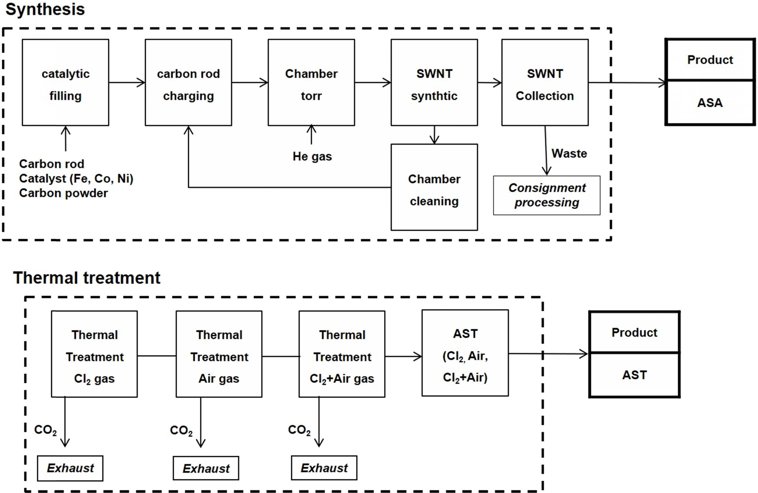
Generally, SWCNTs synthesized by the arc-discharge method constitute remnant amorphous carbon and metal residues, which degrade their properties. Therefore, we employed a heat treatment process to remove these impurities from the as-synthesized SWCNTs. Fig. 1 shows the schematic of the SWCNT synthesis and heat treatment processes used in this study. The SWCNT synthesis process includes filling the catalytic source into the carbon rod, charging the carbon rod in the arc equipment, and setting the pressure of the chamber [40].
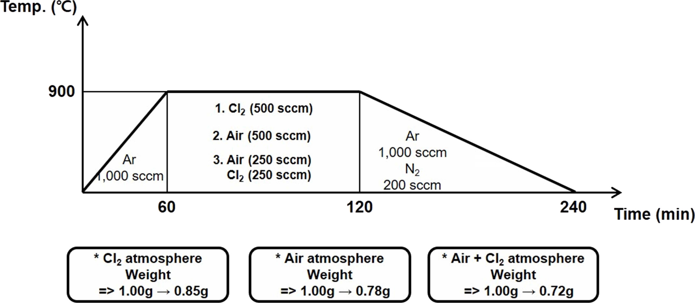
Fig. 2 shows the heat-treatment profiles of the SWCNTs that are thermally refined in the presence of chlorine, oxygen, and chlorine + oxygen gases [41, 42]. In the first case, 1 g of the SWCNTs is loaded into a crucible, which is placed in a furnace for heat treatment. In the first step, the temperature is increased up to 900 °C at a rate of 15 °C/min for 60 min in an argon atmosphere (1,000 sccm). The furnace is then maintained at 900 °C, and chlorine gas is discharged at a flow rate of 500 sccm for 60 min for removing the residual metal and amorphous carbon impurities. Then, argon (1,000 sccm) and nitrogen (200 sccm) are discharged for 120 min to lower the temperature of the furnace to attain the room temperature. At this time, the weight of the sample reduces to 0.85 g (from 1.0 g), indicating that 0.15 g of the impurities are removed. In the second case, the SWCNTs (1 g) are heated up to 900 ℃ at the rate of 15 ℃/min in an argon atmosphere (1,000 sccm). The temperature of the furnace is maintained at 900 ℃, and oxygen gas (500 sccm) is discharged for 60 min to remove the metal and amorphous carbon impurities from the SWCNTs. During the cooling process, argon (1,000 sccm) and nitrogen (200 sccm) gases are discharged into the furnace for 120 min. After cooling, the weight of the sample reduces from 1.0 to 0.78 g. In the third case, the SWCNTs are heated up to 900 ℃ at the rate of 15 ℃/minute for 60 min. The temperature of the furnace is maintained at 900 ℃, and argon (1,000 sccm) is introduced. Then, oxygen (250 sccm) and chlorine (250 sccm) gases are simultaneously discharged into the furnace for 60 min to remove the residual impurities from the SWCNTs. The furnace is then cooled by discharging argon (1,000 sccm) and nitrogen (200 sccm) gases into it for 120 min. The weight of the cooled sample is estimated to be 0.72 g. In all the cases, the weight of the SWCNT samples have decreased after the heat treatment process. This reduction is caused by the removal of the residual impurities (unreacted metal catalyst and amorphous carbon) from the SWCNTs. Thus, it is evident that the heat treatment process yields high-purity SWCNTs. The amount of impurities removed (weight reduction) and the state of removal of the impurities are dependent on the heat-treatment atmospheres. The highest weight reduction is observed in the chlorine + oxygen gas atmosphere [43-45]. Here, chemical reactions that can occur in chlorine gas and oxygen gas can be expressed [46] as follows.
Fe(solid) + Cl2(gas) = FeCl2(gas) (1)
2Fe(solid) + 3Cl2(gas) = 2FeCl3(gas) (2)
C(amorphous carbon, solid) + O2(gas) = CO(gas) + 1/2O2(gas) (3)
C(amorphous carbon, solid) + O2(gas) = CO2(gas) (4)
In short, metal elements such as iron, which remain as impurities, react with chlorine (i.e., (1) and (2)) and are vaporized in the form of iron chloride (i.e., FeCl2 or FeCl3). And, the remaining amorphous carbons react with oxygen (i.e., (3) and (4)) and are vaporized in the form of carbon oxide (i.e., CO or CO2).
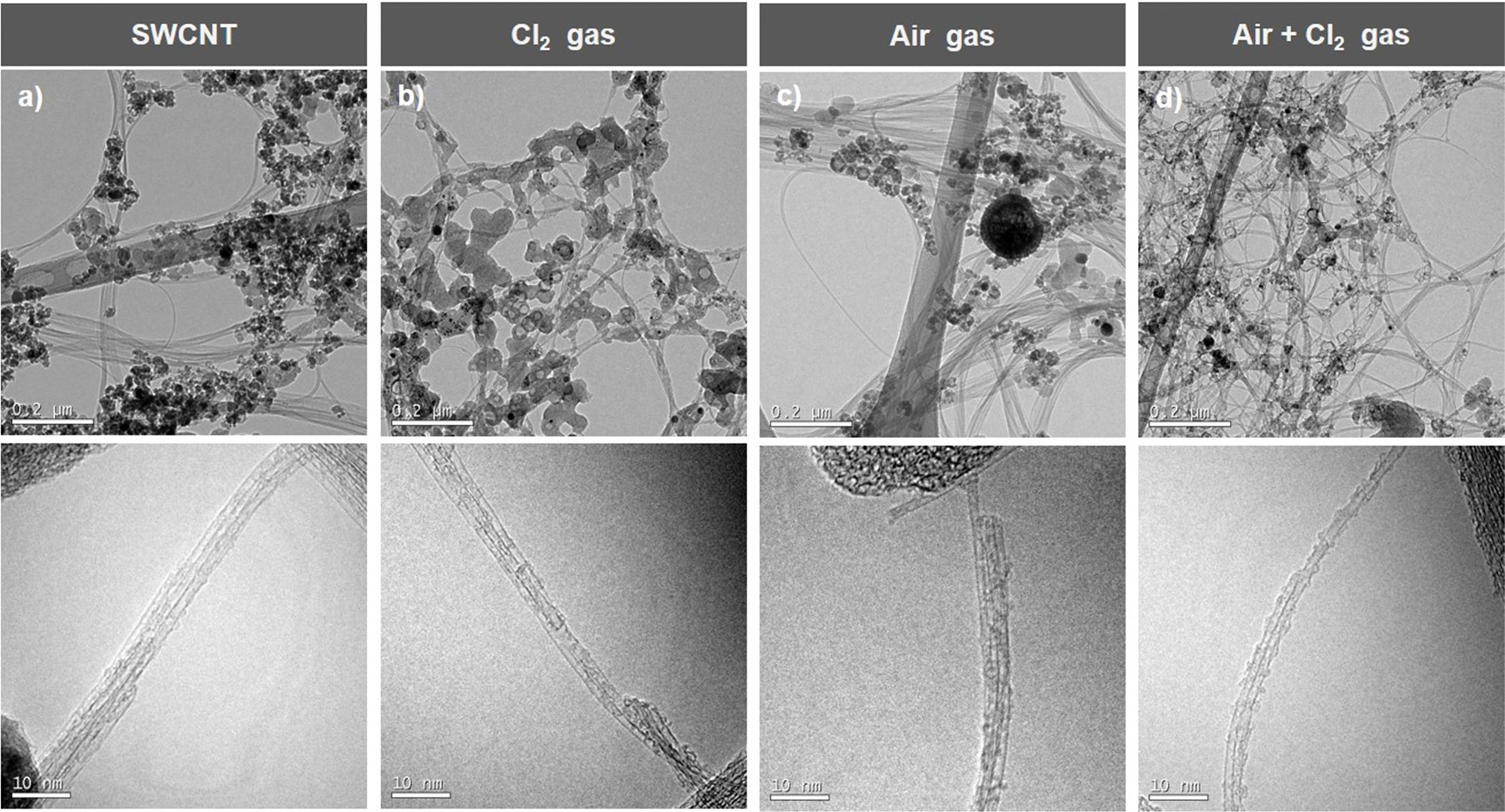
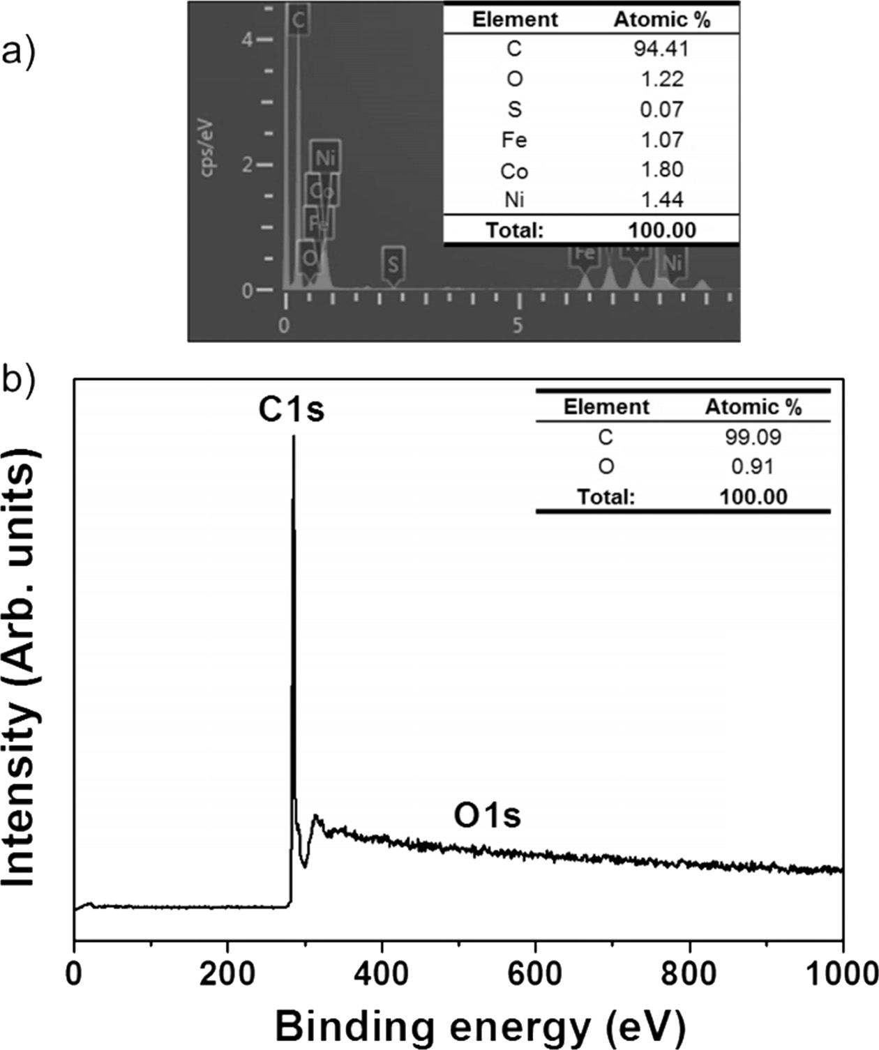
Fig. 3(a) shows the transmission electron microscopy (TEM) image of the SWCNTs fabricated by the arc-discharge method. These SWCNTs demonstrate the unreacted metal catalyst and amorphous carbon impurities. Fig. 3(b) shows the SWCNTs (with reduced impurities) heat-treated in the chlorine atmosphere. Figs. 3(c) and (d) shows the TEM images of the SWCNTs heat-treated in the oxygen atmosphere and oxygen + chlorine atmosphere, respectively. These SWCNTs exhibit remarkably low impurity levels, and hence can be observed evidently. This indicates that significant amounts of impurities are present in the SWCNTs heat-treated in the chlorine and oxygen gas atmospheres individually. However, when chlorine and oxygen gases are used simultaneously, the impurities can be removed significantly. With an increase in the heat-treatment temperature, the materials of the impurities expand, resulting in the formation of gaps in the SWCNTs. Chlorine and oxygen gases permeated into these gaps to remove the impurities. Therefore, the chlorine + oxygen gas atmosphere is identified to be optimum for the heat treatment of the SWCNTs. Fig. 4 is the elemental composition that exactly matches these assertions. When only chlorine gas was used, impurities other than SWCNTs were mixed (Fig. 4(a)). However, when chlorine gas and oxygen gas were used at the same time, pure SWCNTs were obtained (Fig. 4(b)).
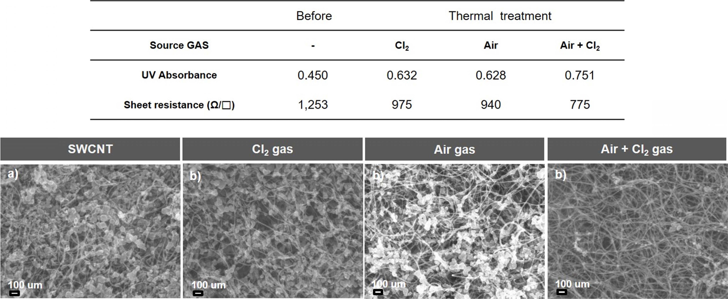
Fig. 5 shows the UV absorbance and sheet resistance results along with the scanning electron microscopy (SEM) images of the SWCNTs. Fig. 5(a) shows the SEM image of the as-synthesized SWCNTs with unreacted metal impurities and amorphous carbon. These SWCNTs exhibit an (average) absorbance of 0.450 and sheet resistance of 1253 Ω/□. Fig. 5(b) shows the SEM image of the SWCNTs heat-treated in the chlorine atmosphere. It is observed from this figure that these SWCNTs exhibit an absorbance of 0.632 and sheet resistance of 975 Ω/□. Fig. 5(c) shows the SEM image of the SWCNTs heat-treated in the oxygen atmosphere. These SWCNTs exhibit an absorbance of 0.628 and sheet resistance of 940 Ω/□. Fig. 5 (d) shows the SEM image of the SWCNTs heat-treated in the oxygen + chlorine gas atmosphere. These SWCNTs exhibit an absorbance of 0.751 and sheet resistance of 775 Ω/□. These results indicate that the oxygen + chlorine gas atmosphere is the most efficient for removing the metal and amorphous carbon impurities from the as-synthesized SWCNTs. These SWCNTs demonstrate a low sheet resistance and high absorbance, which is necessary for practical applications. The lower the sheet resistance, the better the electrical conductivity of SWCNTs. The UV absorbance (absorbing the light by emitting light on the SWCNTs and detecting the amount of light passing through the substance) of SWCNTs is a measure of their purity. The higher the UV absorbance of SWCNTs, the higher their purity. This indicates that the SWCNTs annealed in the oxygen + chlorine gas atmosphere demonstrate the highest purity.
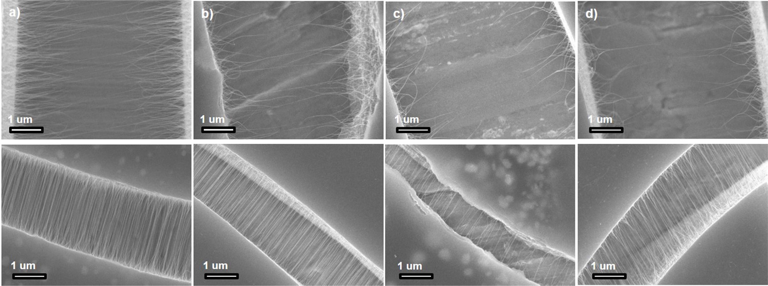
Fig. 6 shows the SEM images of the heat-treated SWCNTs. The specimens for the SEM analysis were prepared by adding the SWCNTs to the UV solution and then dropping the supernatant on a specimen holder. The specimens were dried before obtaining the SEM images. Fig. 6(a) shows SEM image of the as-synthesized SWCNTs. These SWCNTs demonstrate a length of approximately 5-6 μm. The average length is estimated to be approximately 2-3 μm. Fig. 6(b) shows the SEM image of the SWCNTs heat-treated in the chlorine gas atmosphere. These SWCNTs show a maximum length of 4-5 μm. The average length is estimated to be approximately 2 μm. Fig. 6(c) shows the SEM image of the SWCNTs heat-treated in the oxygen gas atmosphere. These SWCNTs show a maximum length of approximately 1-2 μm, and the average length is approximately 1 μm. Fig. 6(d) shows the SEM image of the SWCNTs heat-treated in the oxygen + chlorine gas atmosphere. These SWCNTs demonstrate a maximum length of approximately 1-2 μm, and the average length is estimated to be approximately 1-2 μm. Therefore, it is clear that the SWCNTs heat-treated in the oxygen + chlorine gas atmosphere demonstrate excellent sheet resistance.
|
Fig. 1 Fig. 1. Synthesis and heat treatment of single-walled carbon nanotubes (SWCNTs). |
|
Fig. 2 Fig. 2. Heat treatment of SWCNTs in varied gas atmospheres. |
|
Fig. 3 Fig. 3. TEM images of (a) as-synthesized SWCNTs, (b) SWCNTs heat-treated in Cl2 gas atmosphere, (c) SWCNTs heat-treated in O2 gas atmosphere, (d) SWCNTs heat-treated in Cl2 + O2 gas atmosphere. |
|
Fig. 4 Fig. 4. Elemental composition of SWCNTs in different heat treatment atmospheres. (a) EDX of SWCNTs annealed in Cl2 gas atmosphere, (b) XPS of SWCNTs annealed in Cl2 + O2 gas atmosphere. |
|
Fig. 5 Fig. 5. (Above) UV absorbance and sheet resistance results of SWCNTs before and after the heat treatment. (Below) SEM images of (a) as-synthesized SWCNTs, (b) SWCNTs heat-treated in Cl2 gas atmosphere, (c) SWCNTs heat-treated in O2 gas atmosphere, and (d) SWCNTs heat-treated in Cl2 + O2 gas atmosphere. |
|
Fig. 6 Fig. 6. SEM images of (a) as-synthesized SWCNTs, (b) SWCNTs heat-treated in Cl2 gas atmosphere, (c) SWCNTs heat-treated in O2 gas atmosphere, and (d) SWCNTs heat-treated in Cl2 + O2 gas atmosphere. |
In this study, we synthesized high-purity SWCNTs using the arc-discharge method followed by a heat treatment process. For the heat treatment, the temperature of the furnace was maintained at 900 ℃ for 60 min. The heat treatment was conducted under three different environments: chlorine (500 sccm), oxygen (500 sccm), and chlorine (250 sccm) + oxygen (250 sccm) gases. The maximum lengths of the SWCNTs before and after the heat treatment were estimated at approximately 5–6 and 2-3 μm, respectively. The heat-treated SWCNTs were observed to be shorter than the as-synthesized SWCNTs because of the removal of impurities. Therefore, it is established that heat treatment can be used to synthesize high-purity SWCNTs for various practical applications.
This research was supported by the Basic Science Research Program of the National Research Foundation of Korea (NRF) funded by the Ministry of Education (NRF-2017R1A6A3A11030900 and 2016R1A6A1A03013422).
- 1. M. S. Dresselhaus, G. Dresselhaus and P. Avouris (Eds.), Springer, Berlin (2001).
-

- 2. A. E. Pramono, M. Z. Nura, J. W. M. Soedarsono and N. Indayaningsih, J. Ceram. Process. Res. 20 (2019) 1-7.
- 3. S. A. X. Stango, U. Vijayalakshmi, Ceram. Int. 45 (2019) 69-81.
-
- 4. C.-Y. Liu, A. J. Bard, F. Wudl, I. Weitz and J. R. Heath, Electrochem. Solid State Lett. 2 (199) 577-578.
-
- 5. W. B. Choi, D. S. Chung, J. H. Kang, H. Y. Kim, Y. W. Jin, I. T. Han, Y. H. Lee, J. E. Jung, N. S. Lee, G. S. Park and J. M. Kim, Appl. Phys. Lett. 75 (1999) 3129.
-
- 6. L. Yukui, Z. Changchun, L. Xinghui, Diam. Relat. Mater. 11 (2002) 1845-1847.
-
- 7. J. Y. Kim, M. H. Kim, H. M. Kim, J. Joo, J. H. Choi, Opt. Mater. 21 (2003) 147-151
-
- 8. Y. Zhou, L. Wang, X. Li, X. Wang and H. Jiang, J. Ceram. Process. Res. 19 6 (2018) 479-482.
- 9. R. Socher, B. Krause, M. T. Müller, R. Boldt, P. Pötschke, Polymer 53 2 24 (2012) 495-504.
-
- 10. E.F. Antunes, A.O. Lobo, E.J. Corat, V.J. Trava-Airoldi, Carbon 45 (2007) 913-921.
-
- 11. Y. Chen, J. Zhang, Carbon 49 (2011) 3316-3324.
-
- 12. P. Theilmann, D. J. Yun, P. Asbeck, S. H. Park, Org. Electron. 14 (2013) 1531-1537.
-
- 13. E. Esmizadeh, A. A. Yousefi, G. Naderi, Iran. Polym. J. 24 (2015) 1-12.
-
- 14. Y. Matsuda, J. Tahir-Kheli and W. A. Goddard, J. Phys. Chem. Lett. 1 (2010) 2946-2950.
-
- 15. P.C.P. Watts, D.R. Ponnampalam, W.K. Hsu, A. Barnes, B. Chambers, Chem. Phys. Lett. 378 (2003) 609-614.
-
- 16. A. K. V. Kamat, ACS Nano 1 (2007) 13-21.
-
- 17. G. D. Lee, C.-Z. Wang, J.J. Yu, E. J. Yoon, N. M. Hwang, and K. M. Ho, Phys. Rev. B 76 (2007) 165413.
-
- 18. C. M. Schauerman, J. Alvarenga, B. J. Landi, C. D. Cress, R. P. Raffaelle, Carbon 47 10 (2009) 2431-2435.
-
- 19. P. Nikolaev, O. Gorelik, R. K. Allada, E. Sosa, S. Arepalli and L. Yowell, J. Phys. Chem. C 111 (2007) 17678-17683.
-
- 20. E. G. Gamaly and T. W. Ebbesen, Phys. Rev. B 52 (1995) 2083.
-
- 21. Y. L. Li, I. A. Kinloch, A. H. Windle, Science 304 5668 (2004) 276-278.
-
- 22. T. Guo, P. Nikolaev, A. Thess, D.T. Colbert, R.E. Smalley, Chem. Phys. Lett. 243 (1995) 49-54.
-
- 23. D. A. Walters, L. M. Ericson, M. J. Casavant, J. Liu, D. T. Colbert, K. A. Smith, and R. E. Smalley, Appl. Phys. Lett. 74 (1999) 3803.
-
- 24. J. Ma, J. N. Wang, C. J. Tsai, R. Nussinov, B. Ma, Front. Mater. Sci. 4 (2010) 17-28.
-
- 25. M. Ismail, Y. Zhao, X.B. Yu, A. Ranjbar, S.X. Dou, Int. J. Hydrog. Energy 36 (2011) 3593-3599.
-
- 26. L. Ci, J. Wei, B. Wei, J. Liang, C. Xu, D. Wu, Carbon 39 3 (2001) 329-335.
-
- 27. X. He, W. Gao, L. Xie, B. Li, Q. Zhang, S. Lei, J. M. Robinson, E. H. Hároz, S. K. Doorn, W. Wang, R. Vajtai, P. M. Ajayan, W. W. Adams, R. H. Hauge, J. Kono, Nat. Nanotechnol. 11 (2016) 633-638.
-
- 28. H. Z. Geng, K. K. Kim, K. P. So, Y. S. Lee, Y. Chang and Y. Hee Lee, J. Am. Chem. Soc. 129 (25) (2007) 7758-7759.
-
- 29. M. P. Siegal, D. L. Overmyer, and P. P. Provencio, Appl. Phys. Lett. 80 (2002) 2171.
-
- 30. C. M. Chen, Y. M. Dai, J. G. Huang, J. M. Jehng, Carbon 44 9 (2006) 1808-1820.
-
- 31. Y. H. Yun, V. Shanov, Y. Tu, S. Subramaniam and M. J. Schulz, J. Phys. Chem. B 110 (47) (2006) 23920–23925.
-
- 32. R. G. Lacerda, A. S. Teh, M. H. Yang, K. B. K. Teo, N. L. Rupesinghe, S. H. Dalal, K. K. K. Koziol, D. Roy, G. A. J. Amaratunga and W. I. Milne, Appl. Phys. Lett. 84 (2004) 269.
-
- 33. S. Arepalli, P. Nikolaev, O. Gorelik, V. G Hadjiev, W. Holmes, B. Files, L. Yowell, Carbon 42 (2004) 1783-1791.
-
- 34. M. Chen, H. W. Yu, J. H. Chen, H. S. Koo, Diam. Relat. Mater. 16 (2007) 1110-1115.
-
- 35. E. Castillejos, B. Bachiller-Baeza, M. Pérez-Cadenas, E. Gallegos-Suarez, I. Rodríguez-Ramos, A. Guerrero-Ruiz, K. Tamargo-Martinez, A. Martinez-Alonso, J.M.D. Tascón, J. Alloy. Compd. 536 (2012) S460-S463.
-
- 36. A. Heras, A. Colina, J. López-Palacios, A. Kaskela, A. G. Nasibulin, V. Ruiz, E. I. Kauppinen, Electrochem. Commun. 11 (2009) 442-445.
-
- 37. W. Zhang, L. Johnson, S. R. P. Silva, M.K. Lei, Appl. Surf. Sci. 258 (2012) 8209-8213.
-
- 38. S. Shoji, H. Suzuki, R. P. Zaccaria, Z. Sekkat and S. Kawata, Phys. Rev. B 77 (2008) 153407.
-
- 39. K. Okano, I. Noguchi and T. Yamashita, Macromolecules 43 (2010) 5496-5499.
-
- 40. J. H. Shin, D. W. Shin, S. P. Patole, J. H. Lee, S. M. Park and J. B. Yoo, J. Phys. D-Appl. Phys. 42 (2009) 4.
-
- 41. A. D. Falco, M. L. Fascio, M. E. Lamanna, M. A. Corcuera, I. Mondragon, G. H. Rubiolo, N. B. D’Accorso, S. Goyanes, Physica B 404 (2009) 2780-2783.
-
- 42. P.S. Goh, B.C. Ng, A.F. Ismail, M. Aziz, Y. Hayashi, J. Colloid Interface Sci. 386 (2012) 80-87.
-
- 43. A. Ansón, M. Benham, J. Jagiello, M. A. Callejas, A. M. Benito, W. K. Maser, A. Züttel, P. Sudan and M. T. Martínez, Nanotechnology 15 (2004) 11.
-
- 44. M. J. McAllister, J. L. Li, D. H. Adamson, H. C. Schniepp, A. A. Abdala, J. Liu, M. Herrera-Alonso, D. L. Milius, R. Car, R. K. Prud'homme and I. A. Aksay, Chem. Mater. 19 (18) (2007) 4396-4404.
-
- 45. Pillai, S. K. Augustyn, W. G. Rossouw, M. H. McCrindle, Robert, J. Nanosci. Nanotechnol. 8 (2008) 3539-3544.
-
- 46. I. Barin, Thermochemical data of pure substances (Third Edition), VCH, New York (1995).
-
 This Article
-
2019; 20(4): 388-394
Published on Aug 31, 2019
- Received on Mar 15, 2019
- Revised on Jul 15, 2019
- Accepted on Jul 24, 2019
Services
Shared
Correspondence to
- Sun-Woo Choi b and Changhyun Jin c,d
-
bDepartment of Materials Science and Engineering, Kangwon National University, Samcheok 25913, Republic of Korea
cDivision of Materials Science and Engineering, Hanyang University, Seoul 04763, Republic of Korea
dThe Research Institute of Industrial Science, Hanyang University, Seoul 04763, Republic of Korea
Tel : +82 10 8425 1636
Fax: +82 2 2220 0389 - E-mail: csw0427@kangwon.ac.kr and chjin0910@gmail.com
Clean-Energy Research Institute(CRI), Hanyang University, 222, Wangsimni-ro, Seongdong-gu, Seoul, 04763, Korea
E-mail: jcpr@hanyang.ac.kr