


- Statistical analysis of Vickers hardness and fracture toughness of repeated crack-healing SiC composite ceramics considering economics
Ho-Seok Nam*
Kyoto Institute of Economic Research, Yoshida-hommachi, Sankyo, Kyoto, 606-8501, Japan
This study was carried out to evaluate the repeated crack-healing properties of SiC composite ceramics and to investigate and analyze the Vickers hardness and fracture toughness. SiC composite ceramics were able to heal repeated cracks, but this crack-healing was only suitable up to two times. The oxygen of the three-times crack-healed specimens increased 1158% over that of the as-received specimen. The surface oxide was found to be SiO2, Y2Si2O7, and Al5Y3O12. The Vickers hardness and fracture toughness decreased as the number of crack-healings increased, and the dispersion was increased as well. The Vickers hardness and fracture toughness were analyzed using the two-parameter Weibull statistics. It was concluded that the Weibull distribution can properly describe the Vickers hardness and the fracture toughness of SiC composite ceramics. Ceramic structures that can be repeatedly crack-healed can save costs due to reduced manufacturing costs, replacement costs, shutdowns, etc., which will ensure enormous economic efficiency.
Keywords: SiC ceramics, Repeated crack-healing, Statistical analysis, Vickers hardness, Fracture toughness, Economics
Structural ceramics require high hardness, high temperature resistance and stiffness (elastic modulus), chemical resistance, and excellent wear resistance. Due to these properties, they are applied to the surfaces of space shuttles [1], and are being studied as a blanket material for nuclear fusion furnaces [2-5]. The study of ceramics aims to develop tough, strong, and reliable ceramics. However, as compared to metals and composites, the fracture toughness of ceramics is still poor. That is, ceramics can easily cause brittle fracture in micro cracks. In order to overcome this disadvantage, many researchers are conducting crack-healing studies [6-25].
Crack-healing involves the economic and easy healing of cracks developed before or during service, which can greatly improve the integrity and reliability of the ceramic structure. Surface cracks in composite ceramics can be recovered by heat treatment at high temperature in the atmosphere. That is, SiC monolithic [6-9], Si3N4/SiC [10-16], Al2O3/SiC [17-20], 3Al2O3/SiO2(Mullite)/SiC [21-23] and SiC whisker reinforced ceramics [24-26]. Crack-healing occurred mainly in SiC-added ceramics, and the crack-healing was due to the SiO2 oxide of the surface generated by the oxidation of SiC at high temperature [6-8, 27-29]. For example, alumina and mullite did not exhibit crack-healing behavior, but did show excellent healing ability with the addition of 15 to 20% SiC [17, 18]. Furthermore, even under static or dynamic stresses in a high temperature environment, such crack-healing could occur sufficiently [8,27-29]. Studies on the reliability of heat-treated and corroded ceramics have also been carried out [30-32]. However, these studies are based on one time crack-healing, and there has been no study on repeated crack-healing.
Therefore, this study investigated the crack-healing phenomena through repeated crack-healing using SiC composite ceramics. The Vickers hardness and fracture toughness were analyzed statistically.
Commercially available SiC (Ultrafine grade, Ibiden Co., Japan), Al2O3 (AKP-700, Sumitomo Chemical Co. Ltd., Japan), and Y2O3 (CI Chemical Co., Japan) were used as the starting materials. The mean particle sizes of the SiC, Al2O3, and Y2O3 powders were 0.27 μm, 0.1 μm, and 31 nm, respectively.
The SiC ceramic was prepared using a mixture of 90 wt.% SiC powder and sintering additives (Al2O3 6 wt.%, Y2O3 4 wt.%). The sintering were subsequently hot pressed in N2 gas for one hour via hot-pressing conducted under 35 MPa at 2053 K.
For the crack-healing test, a semielliptical crack was made in the center of the polished face of the specimen by a Vickers indentation of 19.6 N in air. Then, at this time, the Vickers hardness and fracture toughness were determined at the size of cracks. The crack-healing was carried out for one hour at 1173 K in air. Cooling was spontaneous in the furnace [8,9]. In order to analyze the effect of heat treatment, this process was carried out up to three times. In order to investigate the crack-healed surface and the component analysis of crack-healing substances, SEM (scanning electron microscope), EPMA (Electron probe microanalysis), and EDX (Energy Dispersive X-ray) analyses were conducted.
Fracture toughness was calculated using crack length, applied load, Vickers hardness, and elastic modulus. Fracture toughness by Vickers indentation [33-39] was calculated using equations (1) to (4) proposed by Anstis [33, 34, 40]; Evans and Charles [34]; Tanaka [34]; and Niihara, Morena, and Hasselman [41], respectively. These equations were applied to radial-median cracks. The specimens used in this study formed radial-median cracks [30].
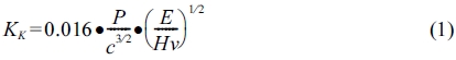
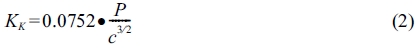
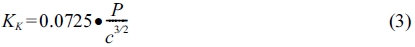
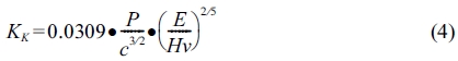
The symbols used in the above equation are as follows: P, the applied load during the Vickers test (N); c, the crack length from the centre of the indentation to the crack tip (m); E, Young's modulus (GPa); and Hv, the Vickers hardness (GPa).
The weibull plot (linear-regression method) is the most common one [42-46]. The cumulative distribution function that gives the probability of P at the Vickers hardness Hv and the fracture toughness KIC can be expressed by the following equation (5):
Where P is the probability of the Vickers hardness Hv and fracture toughness KIC, and α and β are the shape parameter and scale parameter, respectively. x indicates the Vickers hardness Hv and fracture toughness KIC. The scale parameter β describes the Vickers hardness Hv and fracture toughness KIC in 63.2% of the specimen, while α is the shape parameter which gives an indication of data scattering. A higher value of α indicates a smaller variation in the examined property and a high degree of material homogeneity.
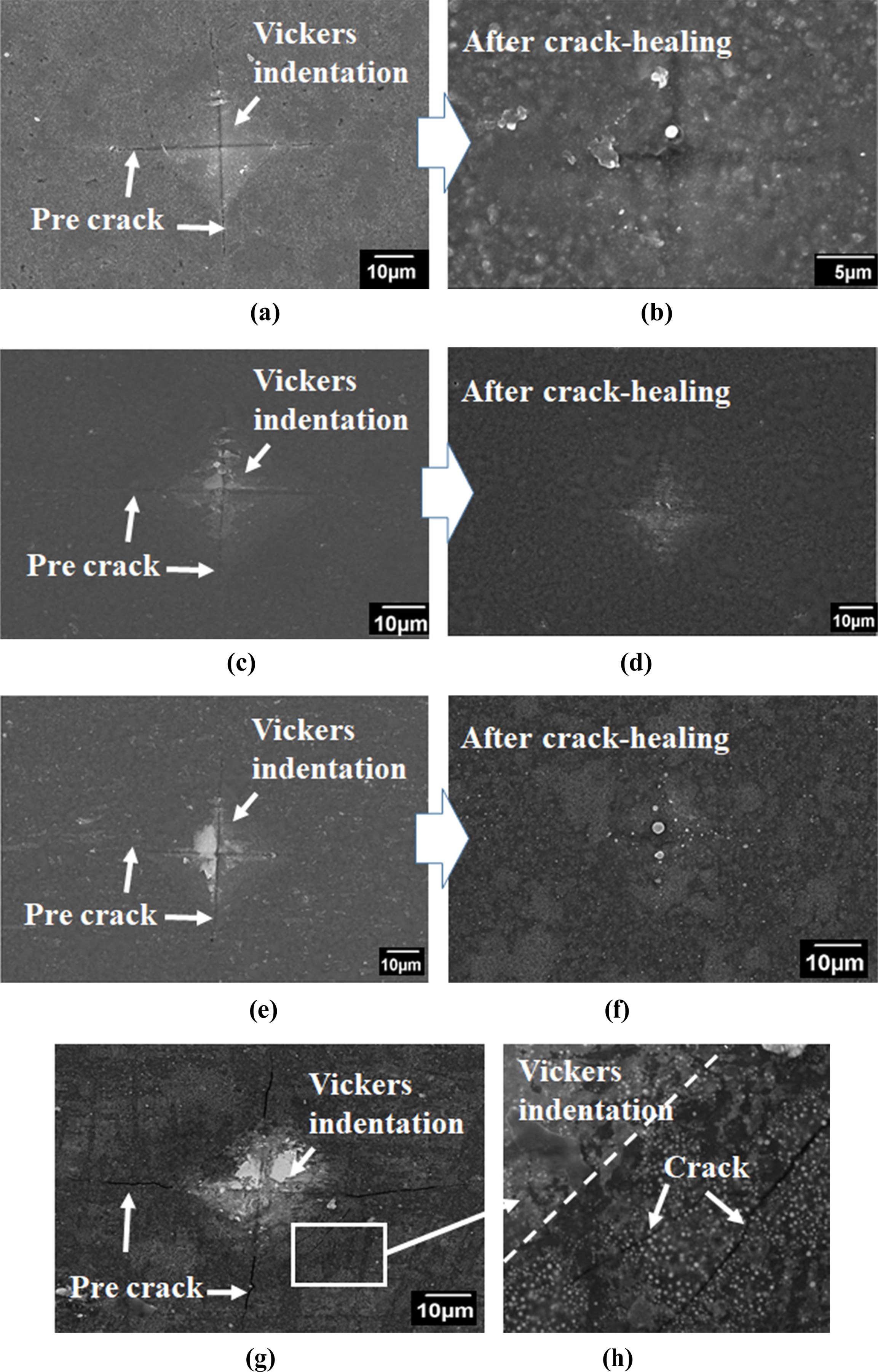
Fig. 1 is a scanning electron microscope photo showing the appearance of the as-received specimen and crack-healing specimen. (a) shows the surface crack and indentation introduced into the as-received specimens with a load of 19.6 N. The fracture surface of the surface cracks shows the shape of semi-elliptical median cracks. (b) shows the appearance of the first crack-healing. That is, it heals the as-received specimen. It can be seen that the cracks caused by the Vickers indentation are all healed and that the indentation is healed as well. (c) shows the surface crack and indentation caused in the healing part of the first crack-healing specimen. The indentation part is covered with SiO2, which is a crack-healing material, but the indentation and crack can be clearly seen. (d) shows the appearance of the second crack-healing. That is, it heals the first crack-healing specimen. It can be seen that the cracks caused by the Vickers indentation are all healed, and that the indentation is also healed. Further, it can be seen that the indentation part is healed more than (b). (e) shows the surface crack and indentation introduced into the healing part of the second crack-healing substances. In the indentation part, SiO2, which is a crack-healing substance, is covered more than (c), but the indentation and crack can be clearly seen. (f) shows the appearance of the third crack-healing. That is, it heals the second crack-healing specimen. It can be seen that the cracks caused by the Vickers indentation are all healed and that the indentation is almost completely healed. It can be seen that the indentation part is healed more than (c). This is considered to be due to the increase of the glassy SiO2 formed by the repeated crack-healing. (g) shows the surface crack and indentation introduced into the healing part of the third crack-healing specimen. In the indentation part, SiO2, which is a crack-healing substance, is covered more than (e), but indentations and cracks can be clearly seen. (h) shows an enlargement of the square portion of (g). Many micro cracks occurred around the indentation. This is because many micro cracks occurred around the indentation part due to degradation by repeated crack-healing, and more amount of SiO2 were formed by crack-healing. Measuring the Vickers hardness was difficult due to the presence of too many micro cracks. As shown below, we obtained six points of data in the third crack-healing specimen, but there was a lot of dispersion. As a result, two times crack-healing is considered to be appropriate.
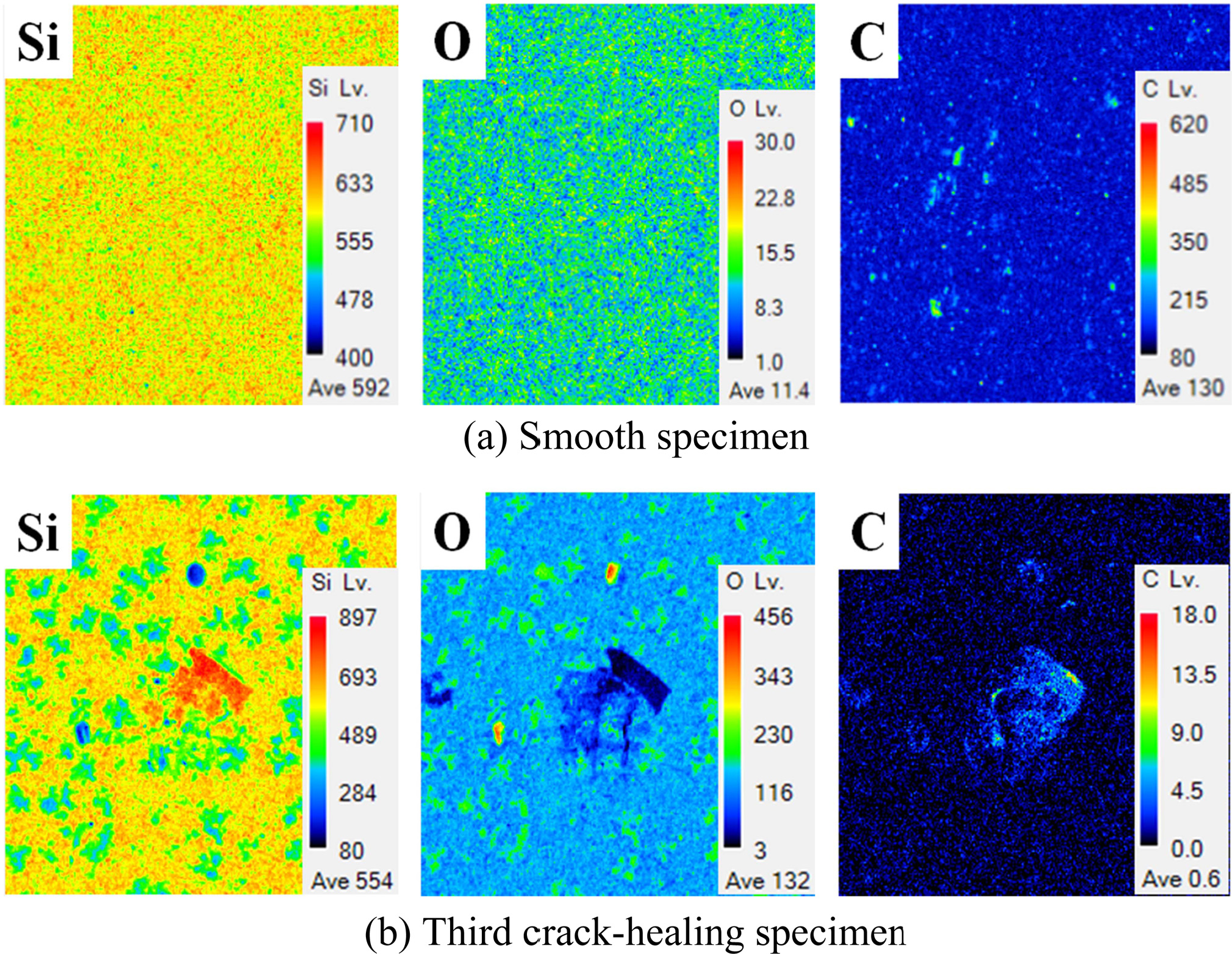
Nam et al. reported that if the crack width is 1.4 μm or less through heat treatment in the atmosphere, it is possible to sufficiently heal, even if the crack length is 450 μm or more [8]. In the SEM photographs before and after the crack-healing shown in Fig. 1, the surface shows that a certain substance covered the cracks. EPMA and XRD analyses were carried out in order to investigate the crack-healing substances on the surface [47, 48]. Fig. 2 shows the elemental distributions and amounts of Si, C, and O on the surface of specimen by EPMA. The as-received specimens were detected to average 592, 11.4, and 130 for Si, O, and C, respectively. However, the third crack-healing specimen was detected to average Si 554, O 132, and C 0.6. The Si, O, and C contents of the third crack-healing specimens were 94%, 1158%, and 0.46% as compared to the as-received specimen, respectively. In other words, Si was slightly decreased by crack-healing, but O was increased enormously. This means that a substantial amount of Si oxide was generated on the surface by crack-healing. Further, C was decreased significantly, and could hardly be detected. It is considered that this was due to the vaporization of CO2 (CO) gas during the crack-healing.
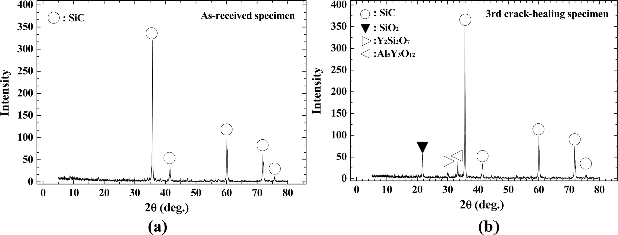
X-ray diffraction (XRD) analysis was carried out using an as-received specimen and a crack-healing specimen to observe the Si oxide produced on the surface. The results are shown in Fig. 3. Only SiC was detected in the as-received specimen. However, the third crack-healing specimen was detected in SiO2, Y2Si2O7, and Al5Y3O12. The reaction formulas related to crack-healing are as follows.
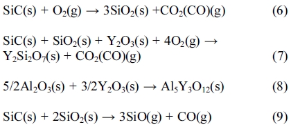
From these results, it can be concluded that the crack-healing occurs from the surface oxidation caused by the heat treatment in the atmosphere, and that the glass phases SiO2, Y2Si2O7, and Al5Y3O12 are directly related in crack-healing.
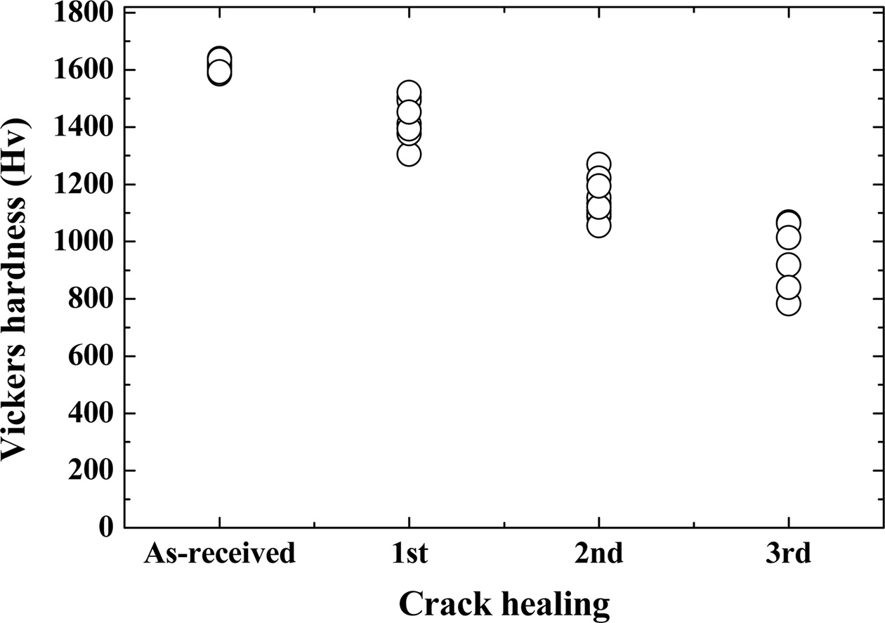
Fig. 4 shows the Vickers hardness of the as-received specimen and the crack-healing specimen. The hardness of the crack-healing specimen gradually decreases as the number of healings increases. The hardness is measured at the crack-healed Vickers indentation part. As described above, the hardness of the indentation part is considered to be small due to the formation of SiO2, which is a healing material, by crack-healing. The as-received specimen showed 1586~1635 Hv, but the first and second crack-healing specimens showed high dispersions of 1305~1503 Hv and 1056~1270 Hv, respectively. In the third crack-healing specimen, many branches of cracks were formed by indentation, and hardness measurement was difficult. This is thought to be caused by the large amount of healing material SiO2 formed in the indentation part by repeated healing. The hardness at this time was 782~1069 Hv with the most dispersion. The mean Vickers hardnesses were reduced by 11.3%, 29%, and 41%, respectively, as compared to the as-received specimen. As described above, the Vickers hardness was gradually decreased due to the oxide formed by the crack-healing.
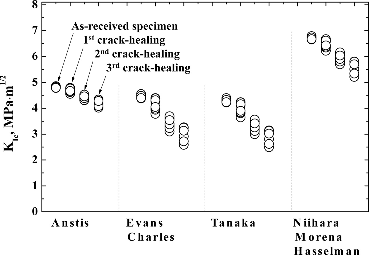
The cracks that originated from the Vickers indentations were used to compute fracture toughness by the Vickers indentation fracture method, using equations (1) to (4) proposed by Anstis; Evans and Charles; Tanaka; and Niihara, Morena, and Hasselman. For Young's modulus E, a value of 410 GPa was assumed. Fig. 5 shows the fracture toughness of the as-received specimen and crack-healing specimen. In each model, the fracture toughness decreased as the number of crack-healings increased, and dispersion was increased as well. The fracture toughness was shown to be in the order of equation (4) > equation (1) > equation (2)  equation (3). The fracture toughness obtained in equation (1) varies from 4.78 to 4.85 for the as-received specimen, from 4.55 to 4.78 for the first crack-healing specimen, from 4.31 to 4.48 for the second crack-healing specimen, and from 4.01 to 4.34 for the third crack-healing specimen. The fracture toughness obtained in equation (2) varies from 4.37 to 4.47 for the as-received specimen, from 3.78 to 4.39 for the first crack-healing specimen, from 3.09 to 3.69 for the second crack-healing specimen, and from 2.58 to 3.26 for the third crack-healing specimen. The fracture toughness obtained in equation (3) varies from 4.22 to 4.38 for the as-received specimen, from 3.64 to 4.23 for the first crack-healing specimen, from 2.99 to 3.47 for the second crack-healing specimen, and from 2.62 to 3.14 for the third crack-healing specimen. The fracture toughness obtained in equation (4) varies from 6.65 to 6.78 for the as-received specimen, from 6.22 to 6.66 for the first crack-healing specimen, from 5.80 to 6.15 for the second crack-healing specimen, and from 5.21 to 5.80 for the third crack-healing specimen.
For evaluating the strength of the ceramics, as a brittle material, a probabilistic evaluation considering the variation distribution is important for improving the accuracy of the assessment. In addition, it can be seen that Vickers hardness and fracture toughness are not a determined value, and change statistically. Accordingly, considering the ease of analysis and the weakest link assumptions, the Weibull statistical analysis must be applied as a two-parameter Weibull distribution.
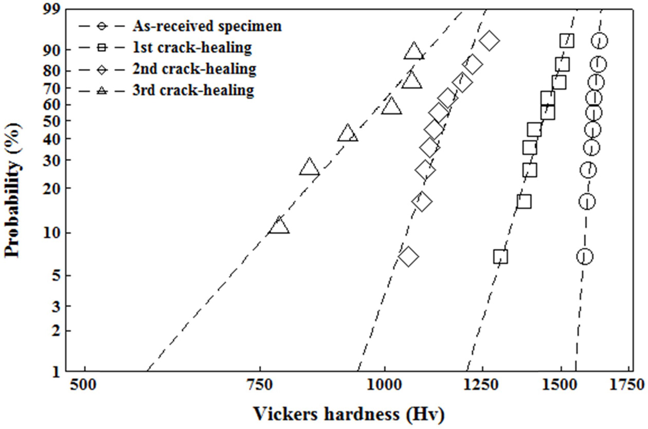
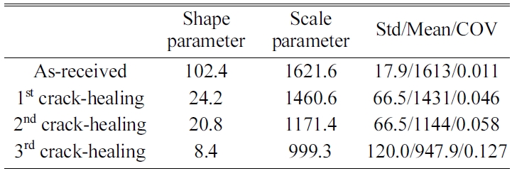
Fig. 6 shows the Vickers hardness of the as-received specimen and the crack-healing specimen according to the Weibull probability. Since Vickers hardness is expressed as a straight line, it can be seen as being applicable to the Weibull probability distribution. Table 1 shows the shape parameter and scale parameters of the Weibull distribution function as estimated from the Vickers hardness of the as-received specimen and the crack-healing specimen. The table also shows the mean, standard deviation (Std), and coefficient of variation (COV) according to statistics. The scale parameters of the as-received specimen were very large, 1621, but those of the crack-healing specimens decreased gradually by 10%, 28%, and 38%, respectively, depending on the number of healings. The shape parameters showed about 102 for the as-received specimens and 24.2 and 20.8 for the first and second crack-healing specimens, respectively. Then, the third crack-healing specimen was small at 8.4. This is because many SiO2 are formed by repeated healing. However, the coefficient of variation showed a tendency opposite to the shape parameter. That is, the as-received specimen showed the smallest value of 0.011, but the crack-healing specimens were 0.046, 0.058, and 0.127, respectively, increasing with the number of healings.
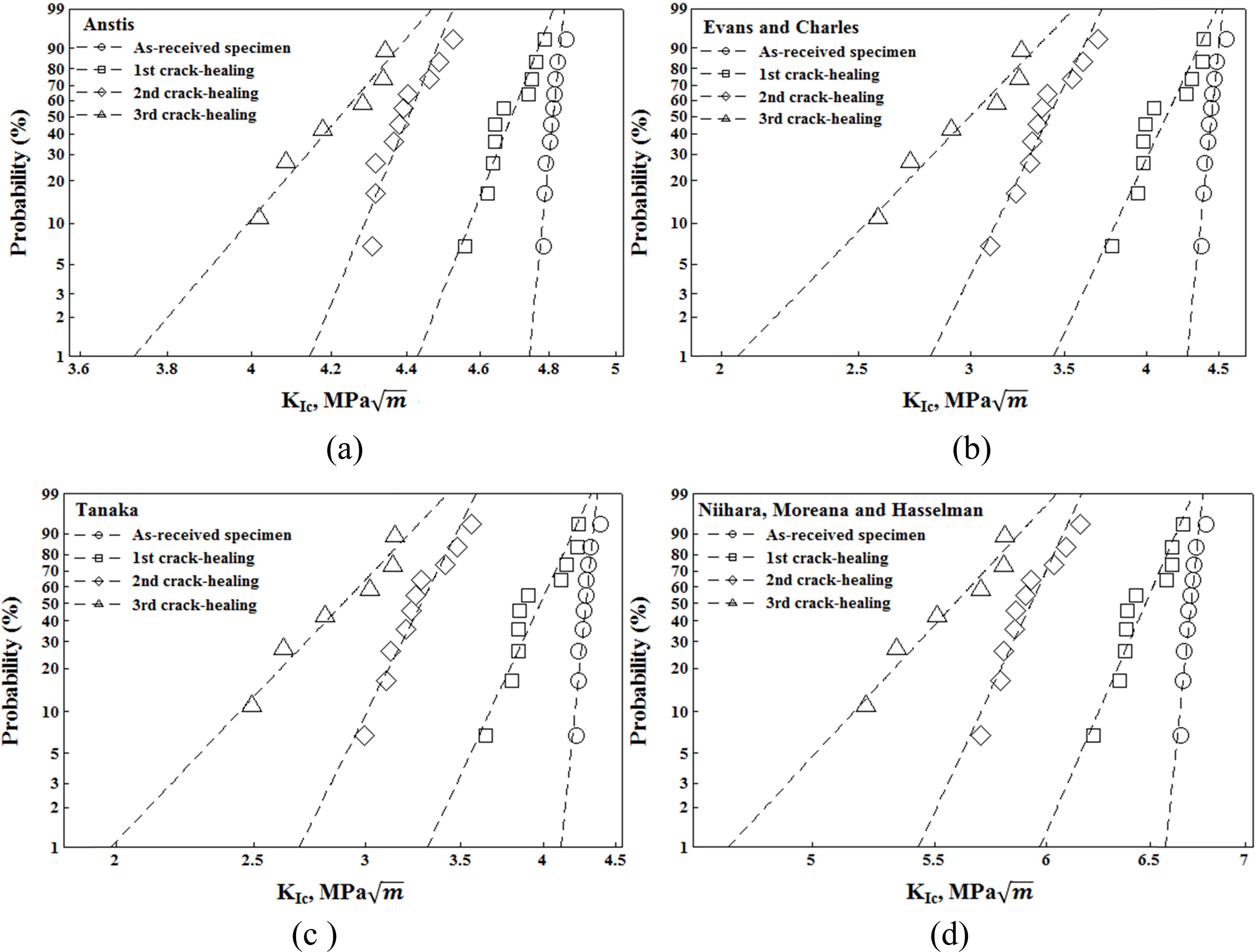
Fig. 7 show the fracture toughness of the as-received specimen and the crack-healing specimen according to the Weibull probability. The fracture toughness was obtained from equations (1), (2), (3), and (4), respectively. Fig. 7 shows that a straight line can be obtained by plotting probability against KIC. Tables 2~5 show the shape parameter and scale parameters of the Weibull distribution function as estimated from the fracture toughness of the as-received specimen and the crack-healing specimen. The table also shows the mean, standard deviation (Std), and coefficient of variation (COV) according to statistics. As shown in Tables 2~5 and Fig. 7, the shape parameter α for the as-received specimen varies from 105.1 (equation (2)) to 286.7 (equation (1)). The first crack-healing specimen varies from 23.0 (equation (2)) to 73.7 (equation (1)). The second crack-healing specimen varies from 21.3 (equation (3)) to 33.7 (equation (1)). The third crack-healing specimen varies from 11.2 (equation (2) and (3)) to 33.7 (equation (1)). The shape parameters showed the order of equation (1) > equation (4) > equation (2)  equation (3).
The scale parameter β for the as-received specimen varies from 4.3 (equation (3)) to 6.7 (equation (4)). That for the first crack-healing specimen varies from 4.0 (equation (3)) to 6.5 (equation (4)). That for the second crack-healing specimen varies from 3.3 (equation (3)) to 6.0 (equation (4)). That for the third crack-healing specimen varies from 3.0 (equation (3)) to 5.7 (equation (4)). The scale parameters showed the order of equation (4) > equation (1) > equation (2) > equation (3). The shape parameters obtained from equations (1) to (4) decreased sharply with increasing numbers of crack-healings, but equations (2) and (3) were similar. The scale parameter and mean were also decreased as the number of crack-healings increased. On the other hand, the coefficient of variation increased.
Generally, fracture toughness as obtained by the considered equations showed a decrease in the observed fracture toughness when the number of crack-healings was increased. Depending on the number of crack-healings and the mathematical equation, the calculated fracture toughnesses of the investigated SiC composite ceramics vary in the range from 4.28 to 4.81 MPa·m1/2 for the as-received specimen, from 3.96 to 6.46 MPa·m1/2 for the first crack-healing specimen, from 3.26 to 5.91 MPa·m1/2 for the second crack-healing specimen, and from 2.87 to 5.56 MPa·m1/2 for the third crack-healing specimen. The lowest fracture toughness was calculated by the Tanaka equation, while the highest values were obtained from the Niihara, Moreana, and Hasselman equation.
Ceramic, which is a structural material for high-temperature materials, is an excellent economical material if cracks generated during service can be used by repeated healing. The Vickers hardness was reduced by 41% as compared to that of the as-received specimen due to the third crack-healing. However, the fracture toughness differed according to the applied evaluation equation. That is, the fracture toughness of the third crack-healing specimen decreased as follows compared to the as-received specimen. Equation (1) is 12.5%, equations (2) and (3) are 32.9%, and equation (4) is 17%. However, in the third crack-healing specimen, the indentation part was excessively embrittled due to the crack-healing substances formed by the repeated healing, and there were many micro cracks formed by Vickers indentation, and the dispersion of hardness and fracture toughness were large. Crack-healing is deemed appropriate up to two times. The crack-healing of the on-site structure can be easily healed by an external heat source such as a torch. Crack-healing ceramic structures can save costs, such as those associated with manufacturing costs, replacement costs, and shutdowns. Therefore, the crack-healing structures can achieve economic efficiency of 200% or more.
|
Fig. 1 SEM micrographs of (a) Vickers indentation of the as-received specimen, (b) first crack-healing specimen, (c) Vickers indentation of first crack-healing specimen, (d) second crack-healing specimen, (e) Vickers indentation of second crack-healing specimen, (f) third crack-healing specimen, (g) Vickers indentation of third crack-healing specimen, (h) enlargement of square zone of (g) |
|
Fig. 2 Surface elemental mapping of as-received specimen and third crack-healing specimen by EPMA. (a) Smooth specimen, (b) third crack-healing specimen. |
|
Fig. 3 Crack-healing substance analysis of as-received specimen and third crack-healing specimen by X-ray diffraction. (a) Smooth specimen, (b) third crack-healing specimen. |
|
Fig. 4 Relationship between Vickers hardness and number of crack-healings. |
|
Fig. 5 Relationship between evaluation equation of indentation fracture toughness and number of crack-healings. |
|
Fig. 6 Weibull plot of Vickers hardness of the as-received specimen and crack-healing specimen. |
|
Fig. 7 Weibull plot of the fracture toughness. (a) Anstis, (b) Evans and Charles, (c) Tanaka, (d) Niihara, Morena, and Hasselman. |
|
Table 1 Statistical analysis of Vickers hardness from the as-received specimen and crack-healing specimen |
In this study, SiC composite ceramics were sintered in order to evaluate their crack-healing behavior, Vickers hardness, and fracture toughness according to repeated crack-healing. The results are as follows. SiC composite ceramics were able to heal repeated cracks, but crack-healing was suitable up to two times. In the third crack-healing specimens, many micro cracks occurred around the indentation. In the EPMA analysis, the oxygen of the third crack-healing specimens increased 1158% over the as-received specimen. The oxide is considered to be a substance directly acting in crack-healing. In the XRD analysis, the surface oxides of the third crack-healing specimens were found to be SiO2, Y2Si2O7, and Al5Y3O12. The Vickers hardness and fracture toughness decreased as the number of cracks-healing increased, and dispersion was increased as well. The fracture toughness values differed according to the evaluation formula. Two-parameter Weibull distribution has been successfully used to describe the statistical variability of Vickers hardness and fracture toughness. Fracture toughness was evaluated by the equations used by Anstis, Evans, and Charles and Tanaka, Niihara, Morena, and Hasselman. The shape parameter of Vickers hardness is in the range from 8.4 to 102.4. That of fracture toughness is in the range from 105.1 (Evans and Charles) to 286.7 (Anstis) in the as-received specimen, from 73.7 (Anstis) to 23 (Evans and Charles) in the first crack-healing specimen, from 69.9 (Anstis) to 21.3 (Tanaka) in the second crack-healing specimen, and from 33.7 (Anstis) to 11.2 (Evans and Charles, Tanaka) in the third crack-healing specimen. Generally, the high values of shape parameter indicate very little data scattering for a particular model and applied load, as well as the homogeneity of the tested material. Ceramic structures that can undergo repeated crack-healing can save costs due to manufacturing costs, replacement costs, shutdowns, etc, which will ensure enormous economic efficiency.
- 1. Nitin P. Padture, Nature Materials 15 (2016) 804-809.
-

- 2. Steven J. Zinkle, Fusion Engineering and Design 74 (2005) 31-40.
-
- 3. M. Singh, Journal of Materials Science Letters 17 (1998) 459-461.
-
- 4. L. L. Snead, T. Nozawa, M. Ferraris, Y. Katoh, R. Shinavski, M. Sawan, Journal of Nuclear Materials 417 (2011) 330-339.
-
- 5. K. W. Nam, J. W. Kim, T. Hinoki, A. Kohyama, J. Murai, T. Murakami, Journal of Nuclear Materials 417 (2011) 353-355.
-
- 6. Y. Korous, M. C. Chu, M. Nakatani and K. Ando, J. Am. Ceram. Soc. 83 (2000) 2788-2792.
-
- 7. Y. W. Kim, K. Ando and M. C. Chu, J. Am. Ceram. Soc. 86 (2003) 465-470.
-
- 8. K. W Nam, J. S Kim, 2010, Materials Science and Engineering: A 527 (2010) 3236-3239.
-
- 9. K. W Nam, J. S Kim and S. W Park, Materials Science and Engineering: A 527 (2010) 5400-5404.
-
- 10. K. W Nam, M. K Kim, S. W Park, S. H Ahn, J. S Kim, Materials Science and Engineering: A 471 (2007) 102-105.
-
- 11. K. Ando, K. Houjyou, M. C. Chu, S. Takeshita, K. Takahashi, S. Sakamoto and S. Sato, J. Eur. Ceram. Soc. 22 (2002) 1339-1346.
-
- 12. K. Ando, K. Takahashi, S. Nakayama and S. Saito, J. Am. Ceram. Soc. 85 (2002) 2268-2272.
-
- 13. K. Ando, M. C. Chu, S. Matsushita and S. Sato, J. Eur. Ceram. Soc. 23 (2003) 997-984.
-
- 14. K. Ando, T. Ikeda, S. Sato F. Yao and Y. Kobayashi, Fatigue & Fract Eng Mat. 21 (2002) 119-122.
-
- 15. K. Takahashi, K. Ando, H. Murase, S. Nakayama and S. Saito, J. Am, Ceram, Soc. 88 (2005) 645-651.
-
- 16. K. Takahashi, Y. S. Jung, Y. Nagoshi and K. Ando, Materials Science and Engineering A 527 (2010) 3343-3348.
-
- 17. H. S. Kim, M. K. Kim, S. B. Kang, S. H. Ahn and K. W. Nam, Materials Science and Engineering A 483-484 (2008) 672-675.
-
- 18. K. W. Nam, J. Ceram. Processing Research 11 (2010) 471-474.
-
- 19. T. Osada, W. Nakao, K. Takahashi and K. Ando, Journal of the European Ceramic Society 27 (2007) 3261-3267.
-
- 20. C. Zdenek, F. Petr, K. Ando and D. Ivo, Journal of the European Ceramic Society 28 (2008) 1073-1077.
-
- 21. S. K. Lee, M. Ono, W. Nakao, K. Takahashi and K. Ando, J. Euro. Ceram. Soc. 25 (2005) 3495-3502.
-
- 22. W. Nakao, S. Mori, J. Nakamura, K. Takahashi, K. Ando and M. Yokouchi, J. Am. Ceram. Soc. 89 (2006) 1352-1357.
-
- 23. K. Ando, K. Furusawa, K. Takahashi and S. Sato, J. Euro. Ceram. Soc. 25 (2005) 549-558.
-
- 24. K. Takahashi, M. Yokouchi, S. K. Lee and K. Ando, J. Am. Ceram. Soc. 86 (2003) 2143-2147.
-
- 25. W. Nakao, M. Ono, S. K. Lee. K. Takahashi and K. Ando, J. Euro. Ceram. Soc. 25 (2005) 3649-3655.
-
- 26. W. Nakao, S. Mori, J. Nakamura, K. Takahashi, K. Ando and Y. Masahiro, J. Am. Ceram. Soc. 89 (2006) 1352-1357.
-
- 27. F. F. Lange, J. Am. Ceram. Soc. 53 (1970) 290.
-
- 28. T. E. Easler, R. C. Bradt and R. E. Tressler, J. Am. Ceram. Soc. 64 (1981) 731-734.
-
- 29. N. S. Jacobson, K. N. Lee and D. S. Fox, J. Am. Ceram. Soc. 75 (1992) 1603-1611.
-
- 30. S. H. Ahn, S. C. Jeong and K. W. Nam, J. Ceram. Processing Research 17 (2016) 994-998.
- 31. S. C. Jeong, S. H. Ahn and K. W. Nam, J. Ceram. Processing Research 18 (2017) 506-520.
- 32. S. H. Ahn and K. W. Nam, J. Ceram. Processing Research 18 (2017) 646-658.
- 33. G. R. Anstis, P. Chantikul, B. R. Lawn and D. P. Marshall, J. Am. Ceram. Soc. 64 (1981) 533-538.
-
- 34. A. Nastic, A. Merati, M. Bielawski, M. Bolduc, O. Fakolujo and M. Nganbe, J. Mater. Sci. Technol. 31 (2015) 773-783.
-
- 35. P. Chantikul, G. R. Anstis, B. Lawn and D. B. Marshall, J. Am. Ceram. Soc. 64 (1981) 539-543.
-
- 36. K. Strecker, S. Ribeiro and M. J. Hoffmann, Mat. Res. 8 (2005) 121-124.
-
- 37. G. D. Quinn, “Fracture toughness of ceramics by the Vickers indentation crack length method,” Ceram. Eng. Sci. Proc., John Wiley & Sons, Inc., New Jersey, (2007) pp. 45-62.
-
- 38. D. Casellas, M. M. Nagl, L. Llanes and M. Anglada, J. Am. Ceram. Soc. 88 (2005) 1958-1963.
-
- 39. Y. Du, X. Yang, H. Zhang, X. Zhang, M. Zhao, H. Chen, S. Ouyang and B. Li, J. Ceram. Processing Research 17 (2016) 1243~1248.
- 40. M. C. Corrêa de Sá e Benevides de Moraes, C. N. Elias, J. D and L. Guimarães de Oliveira, Mat. Res. 7 (2004) 643-649.
-
- 41. K. Niihara, R. Morena and D. P. H. Hasselman, J. Mat. Sci. Letters 1 (1982) 13-16.
-
- 42. A. Saghafi, A. R. Mirhabibi and G. H. Yari, Theor. Appl. Fract. Mech. 52 (2009) 2-180.
-
- 43. R. Langlois, J. Mater. Sci. Letters 10 (1991) 1049-1051.
-
- 44. D. Wu and H. Jiang, J. Mater. Sci. 22 (2003) 1745-1746.
-
- 45. J. Gong, J. Mater. Sci. Letters. 16(1997) 875-876.
-
- 46. K. W. Nam and J. S. Kim, J. Ceram. Processing Research 11 (2010) 20~24.
- 47. M. K. Kim, S. B. Kang, S. H. Ahn and K. W. Nam, Solid State Phenomena 124-126 (2007) 719-722.
-
- 48. K. W. Nam, J. S. Kim, S. Won Park, Materials Science and Engineering A 527 (2010) 5400-5404.
-
 This Article
-
2019; 20(4): 379-387
Published on Aug 31, 2019
- Received on Mar 8, 2019
- Revised on Jul 5, 2019
- Accepted on Aug 2, 2019
Services
Shared
Correspondence to
- Ho-Seok Nam
-
Kyoto Institute of Economic Research, Yoshida-hommachi, Sankyo, Kyoto, 606-8501, Japan
Tel : +81-75-753-7175
Fax: +81-75-753-7178 - E-mail: namhs85@naver.com
Clean-Energy Research Institute(CRI), Hanyang University, 222, Wangsimni-ro, Seongdong-gu, Seoul, 04763, Korea
E-mail: jcpr@hanyang.ac.kr