- Formation behavior of indium hydroxide powder synthesized by a precipitation method
Hyung-Ryul Parka,*, Won-Jun Leeb, Kwang-Bo Shimc, Hae-Jin Hwangb and Jin-Ho Kima
aSchool of New Materials Engineering Kyungpook National University 41566, Korea
bSchool of Material Science and Engineering, Inha University, Incheon 22212, Korea
cDepartment of Material Science and Engineering, Hanyang University Seoul 04763, Korea
Powders were obtained using an indium chloride solution and were characterized as a function of precipitation pH, aging time, and concentration of the liquid synthetic medium. Indium hydroxide (In(OH)3) and indium oxide hydroxide (InOOH) co-existed in the pH range of 5 to 8, but only indium hydroxide was present at pH 9 and 10. The crystallite size of In(OH)3 had a stronger dependence on pH than on the concentration of the reaction medium compared to InOOH. Hence, the relative crystallite size of In(OH)3 increased significantly with increasing pH compared to that of InOOH, which barely changed with increasing concentration and pH. Although the crystallite size of In(OH)3 increased slightly with increasing precipitate aging time, the specific surface area decreased significantly. These results can help control the synthesis of indium oxide particles used to make indium tin oxide targets.
Keywords: Indium hydroxide, Indium oxide hydroxide, Precipitation method
Indium tin oxide (ITO) is the most widely used transparent conductive oxide (TCO) owing to its high optical transparency in the visible light region, electrical conductivity similar to that of metals, and high reflectance in the infrared region [1]. Indium tin oxide is a representative TCO material with a bandgap >3.5 eV and high electrical conductivity. One of its most important properties is its high light transmission (>85%) within the visible spectrum [2-4]. In addition, ITO exhibits high electrical conductivity and optical transparency in the visible light region [4]. As such, ITO is not only used in pixel electrodes or common electrodes in flat displays including organic light emitting diodes and liquid crystal displays, but also in other areas such as liquid crystal cells, gas sensors, and solar cells [5-8].
Indium oxide (In2O3) nanopowders are essential starting materials for preparing ITOs; they have excellent electrical mobility with high intrinsic electron concentration and consist of very small particles that show the possibility of quantum confinement effects. Indeed, In2O3 has attracted much attention among researchers for its widespread application in solar cells [9], field-emission displays [10], lithium-ion batteries [11], nanoscale biosensors [12], non-volatile nanofloating gate memory devices [13], gas sensors [14], optoelectronics[15], photocatalysis [16], and field effect transistors [17]. Nanosized indium oxide particles can be synthesized by various methods such as sonochemical synthesis [18], chemical vapor deposition [19], hydrothermal synthesis [20], and precipitation [21]. Among these, the precipitation method is relatively simple and offers an economical advantage due to its high production efficiency.
In this method, indium metal is first dissolved in hydrochloric acid (HCl) and then neutralized with sodium hydroxide to form indium hydroxide powder. Hence, the characteristics of indium oxide powders are largely influenced by those of the precursor indium hydroxide powder. Indium oxide powder is the most important starting material for the production of ITO targets and is a key factor that determines the sintering density. In order to produce an ITO target having a high density, it is necessary to minimize the particle size of indium oxide, and it is also necessary to use a monodispersed powder having a uniform particle size to increase the density [22].
In this study, a high-purity (>99.99%) indium hydroxide powder was synthesized by a precipitation method that can easily be implemented in mass production. The purpose of this study is to determine the characteristics of the precipitates obtained by changing precipitation processing variables including pH, concentration, and aging time, and to investigate the formation behavior of indium hydroxide powders.
Indium chloride solutions with concentrations of 0.1, 0.25, 0.75, and 1 M were prepared by dissolving indium metal (In, 99.99%, Top Material, Korea) in hydrochloric acid (HCl, SAMCHUN Chemical, 35-37%, extra pure grade, Korea). To each indium chloride solution, a sodium hydroxide solution (NaOH, 2 mol) was added at a rate of 3 mL/min to obtain solutions with pH values of 5, 6, 7, 8, 9, and 10, and the obtained precipitates appeared as a white solid. To observe the aging effect on the precipitates, the aging time was varied from 0 to 40 h. A centrifuge was used to process the gel-type precipitate, which was dried in an oven for 24 h. The powder cohered during drying and was pulverized using agate induction.
X-ray diffraction (XRD, Rigaku, D/2500VL/PC, Japan) was used to confirm the crystal type and crystallite size of the processed precipitates (Cu Kα; λ = 1.5402 nm). In addition, the Scherrer equation (equation (1)) was used to calculate the crystallite size:

where β is the full width at half maximum (FWHM), Κ is the shape factor, λ is the wavelength (Cu Kα1 = 1.54056 Å), and τ is the crystallite size. We also investigated the influence of XRD equipment factor using standard samples in advance to calculate the exact crystallite size. α-quartz powder with a size of 25μm or more without lattice strain was used as a standard sample. The sample was annealed at 800°C to remove the residual stress of the sample. We calculated the influence of XRD equipment factor, which depends on X-Ray diffraction angle. Transmission electron microscopy (TEM, JEOL, 200 kV, JEM-2100F, Japan) was used to confirm the shape, size, and lattice characteristics of the particles. The Brunauer-Emmett-Teller (BET) specific surface area of the produced powders was also measured (Micromeritics Tristar Ⅱ, Instrument Co., Norcross, GA, USA).
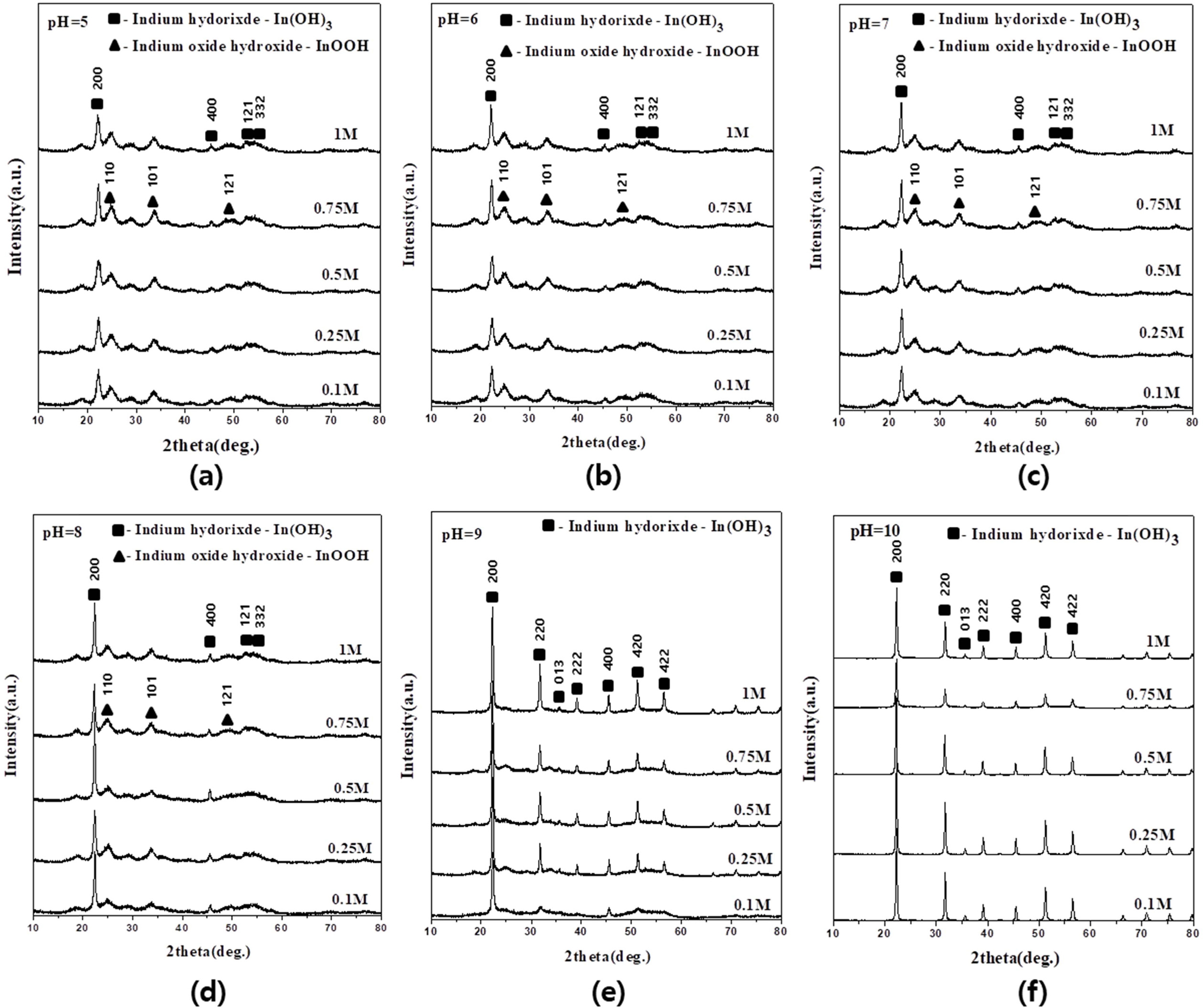
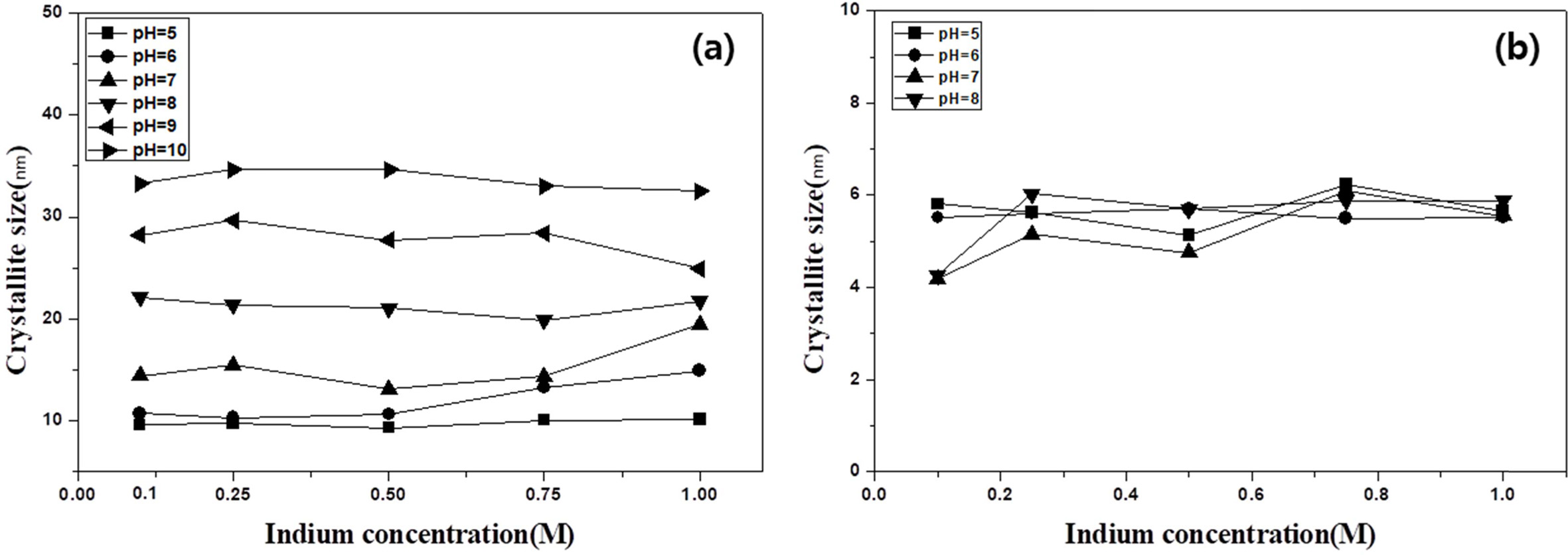
The XRD patterns of the precipitates obtained from indium chloride solutions with concentrations of 0.1 to 1 M at different pHs are shown in Fig. 1. Indium hydroxide (In(OH)3) (JCPDS No. 71-2194) and indium oxide hydroxide (InOOH) (JCPDS No.71-2276) co-existed under all conditions [23]. In(OH)3 and InOOH have a cubic and orthorhombic crystal structure, respectively. The FWHM of the XRD peaks corresponding to the In(OH)3 phase was smaller than the FWHM of the XRD peaks corresponding to indium oxide hydroxide. The crystallite size of each phase was calculated using equation (1) at 2θ = 22.2° for the main peak of In(OH)3 and 2θ = 25.1° for that of InOOH. Fig. 2 shows the calculated sizes as a function of concentration at different pH values. The crystallite size of In(OH)3 increased from 9 to 36 nm with the increasing pH of the indium chloride solution, but there was almost no difference in crystallite size with different concentrations, as shown in Fig. 2(a). The crystallite size of InOOH was almost independent of the concentration and pH, with only small changes of 4-7 nm. At pH 9?10, a slight decrease was observed at 0.1 M. InOOH was not observed at pH 9 and 10, as shown in Fig. 2(b). These results thus indicate that the increase in the crystallite size of In(OH)3 depends on the pH, whereas neither the pH nor the concentration affect the crystallite size of InOOH.
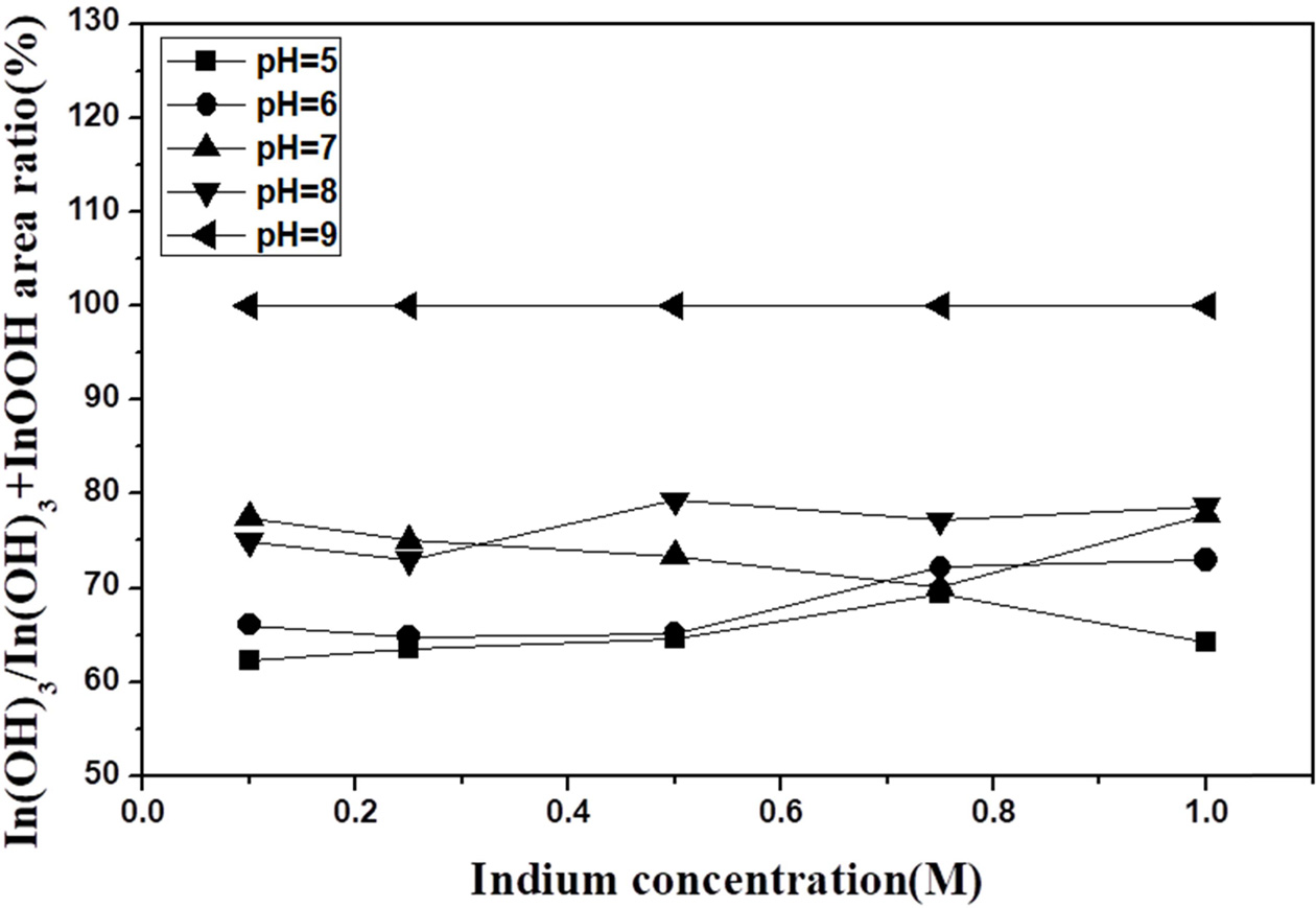
Fig. 3 shows the derived ratio of the integrated areas of the XRD peaks corresponding to In(OH)3 and InOOH with increasing concentration for different pH values. As both the concentration and pH increased, the ratio of In(OH)3 to InOOH varied between 1 and 2, and at pH 9, only the In(OH)3 phase was present. The above results can be correlated to a pH solubility curve; as the pH increases, the In(OH)3 concentration increases as more OH- is generated as In3+, In(OH)2+, In(OH)2+, In(OH)3, and In(OH)4- in the solution [24]. In(OH)2+ ions react with O2 to form an InOOH precipitate. The increase in pH implies an increase in the OH-. The reason for the presence of InOOH between pH 5 and 8 is most likely related to the In(OH)2+ ions reacting with O2 to form an InOOH precipitate. It is assumed that In(OH)3 is present due to the complete disappearance of InOOH at pH 9 with sufficient OH- ions.
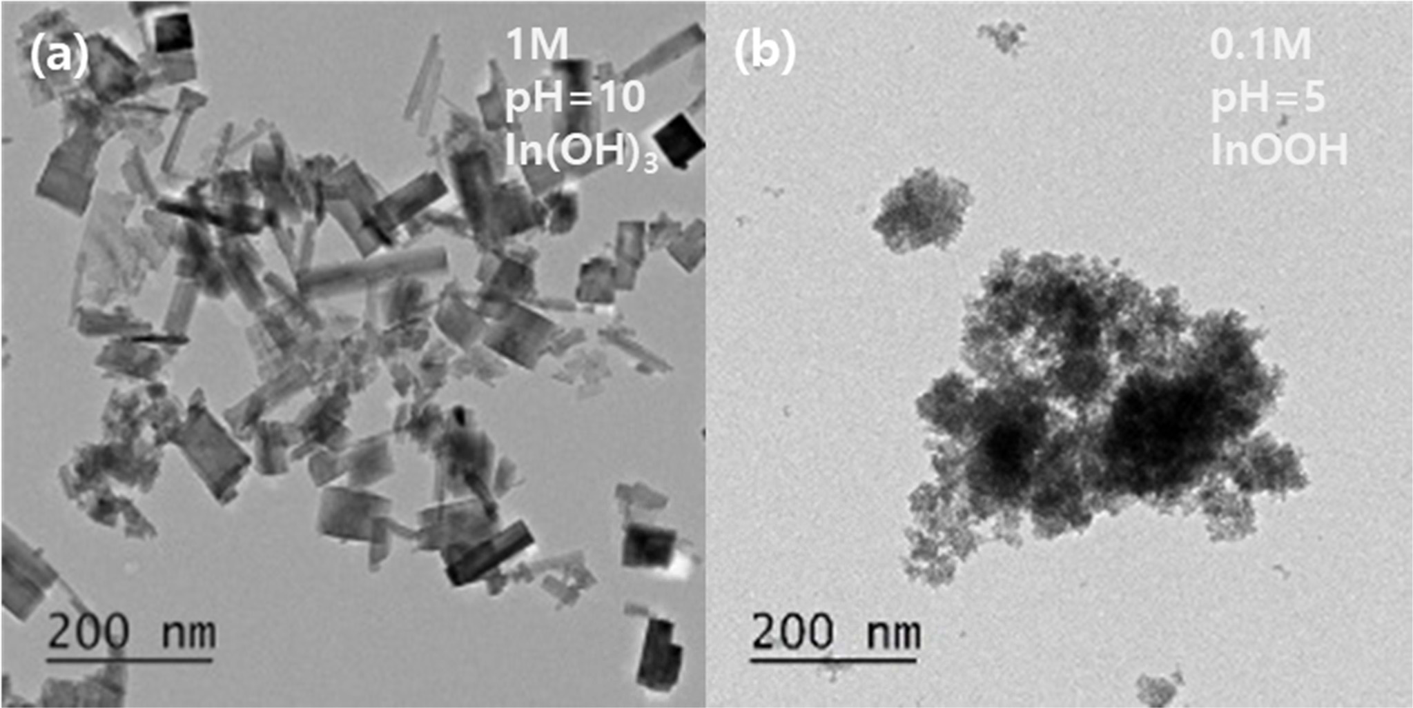
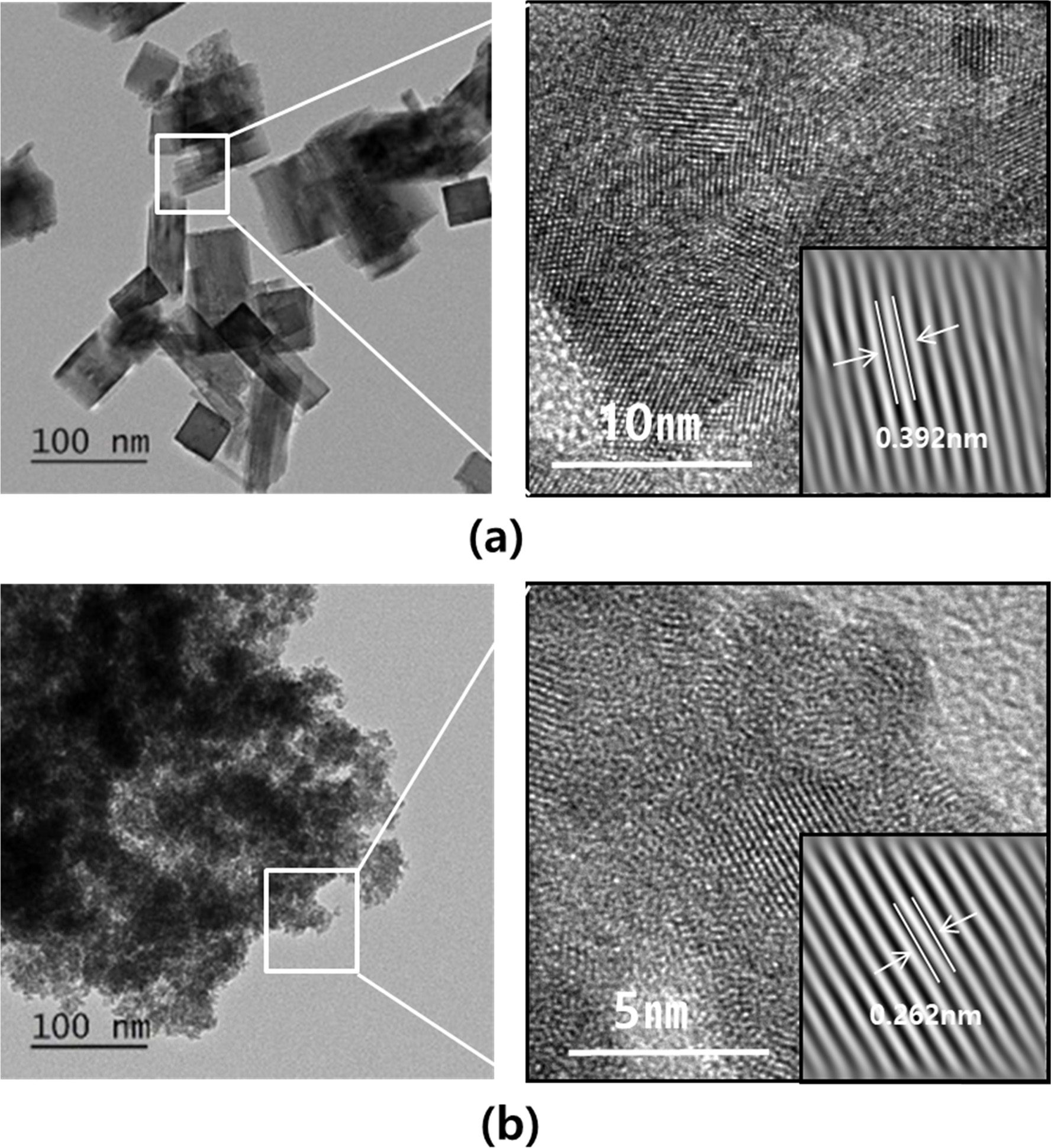
Fig. 4 shows the TEM images of powders synthesized from two different solutions having a concentration of 1 M and a pH of 10 and a concentration of 0.1 M and a pH of 5, respectively. In both solutions, spherical particles with a diameter of 3-5 nm and rectangular particles with dimensions of ~40 nm × 100 nm were observed. The size of the spherical particles corresponded to the crystallite size of InOOH. However, the size of the rectangular particles did not match the crystallite size of InOOH or In(OH)3. A high-resolution image of the rectangular and spherical particles is shown in Fig. 5. The rectangles did not appear as a single crystal but rather consisted of single crystals and a noncrystalline species. The size of the single crystal was approximately 10-15 nm and was almost the same as the crystallite size of In(OH)3. The lattice distance shown in Fig. 5(a) is 0.392 nm, which is equal to the d200 value of In(OH)3, indicating that the rectangular particles were polycrystals of In(OH)3. The lattice distances of the spherical particles with a diameter of 5 nm were also investigated. As shown in Fig. 5(b), the lattice distance of 0.262 nm agrees with the dl10 value of InOOH, indicating that the spherical particles were monocrystalline InOOH.
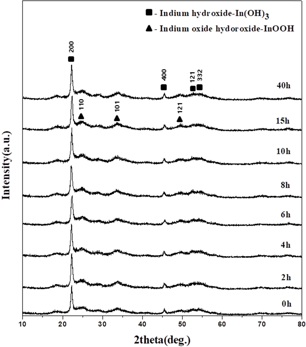
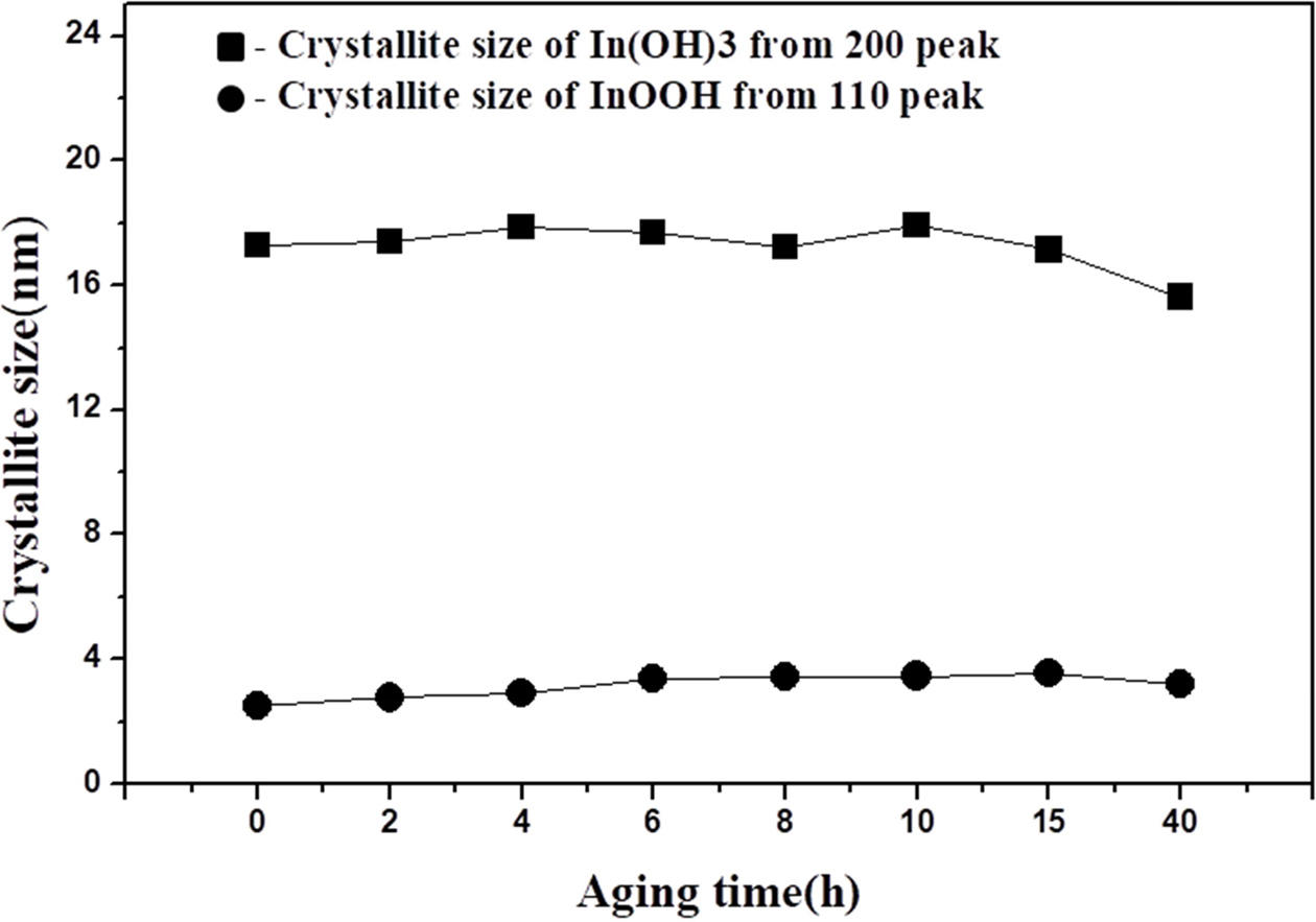
Fig. 6 shows the XRD patterns of powders obtained after different aging times. The precipitates were obtained by titrating the liquid indium chloride solution (0.25 M) to pH = 7 with ammonium hydroxide solution. The two types of particles mentioned above were present in all samples. The crystallite sizes of both particles did not change with the aging times (Fig. 7). The crystallite sizes of In(OH)3 and InOOH were within a 16.3-18.1 nm and 2.5-3.6 nm range, respectively. These results are consistent with other observations in our study.
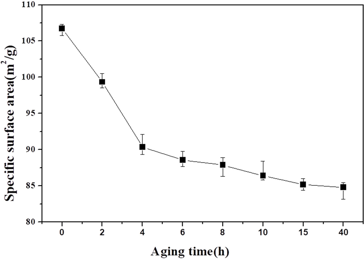
Fig. 8 shows the specific surface areas of the powders obtained after different aging times. The specific surface area of the powder obtained without solution aging was 106.7 m2 g-1, but was reduced to 99.34 m2 g-1 after aging for 4 h and decreased to 99.34 m2 g-1 after further aging. Thus, the specific surface area significantly decreased as the aging time increased. For the specific surface area to decrease without the crystallite size increasing, the particle size should increase to a polycrystalline size. These results show the significance of controlling the size of the indium oxide powder obtained by heat treatment of a powder optained by drying a precipitate.
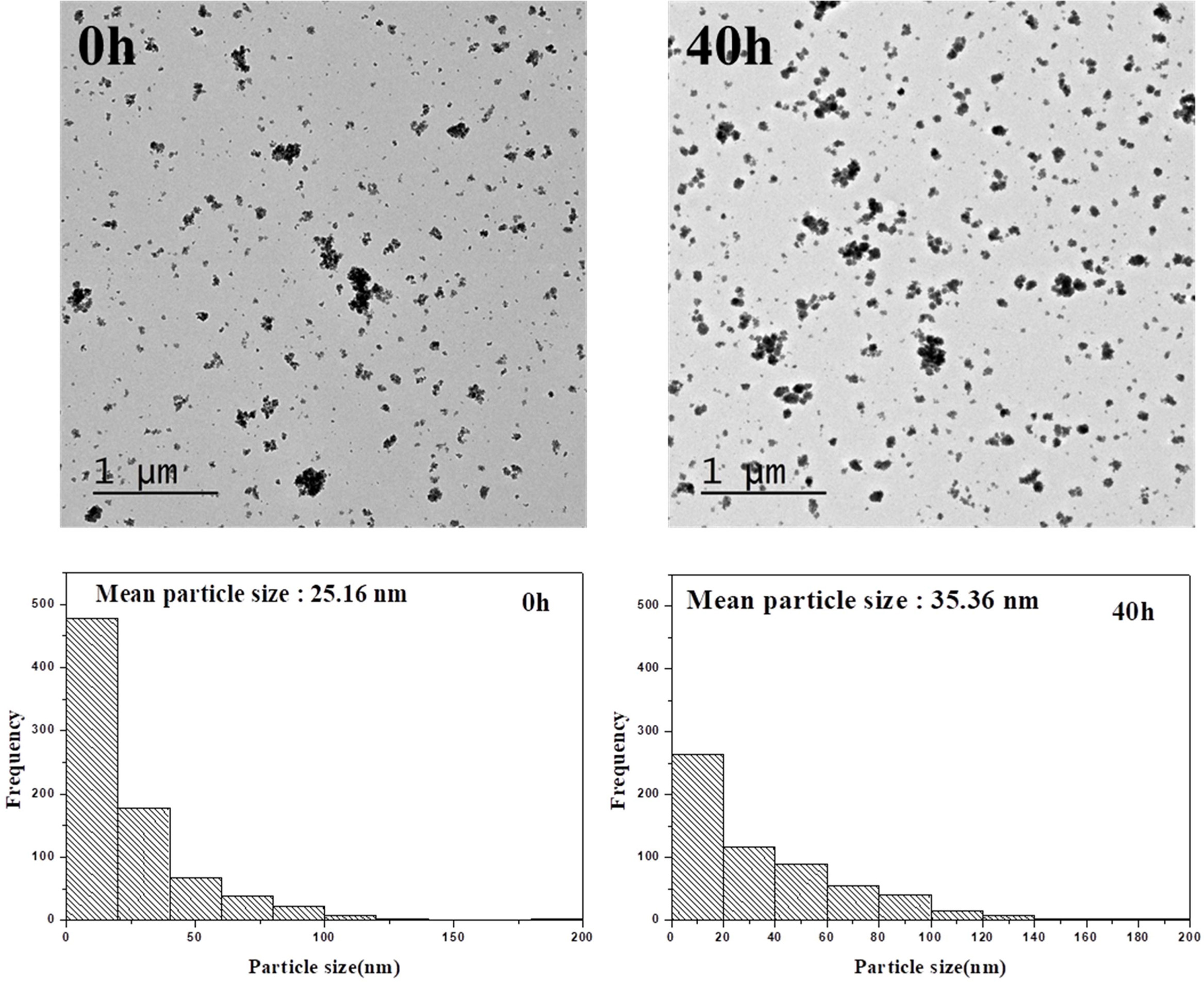
To determine the effect of aging time on particle size, the powders aged from 0 to 40 h were observed by TEM. The un-aged powder had weaker cohesion and a smaller particle size than the powders aged for 40 h (Fig. 9). The initial deposited materials consisted of very fine nanoscale particles, which are assumed to cause the unstable, high-surface-energy state. This indicates that the particles cohere more strongly to reduce the surface energy and increase the particle size as the aging time increases. Once these particles reach a certain size, cohesion stops, and the particle size remains almost constant. Therefore, the aging time influences both the cohesion of In(OH)3 and InOOH particles and the size of the resulting indium oxide particles.
|
Fig. 1 XRD patterns of powders obtained at pH (a) 5, (b) 6, (c) 7, (d) 8, (e) 9, and (f) 10 in 0.1, 0.25, 0.5, 0.75, and 1 M solutions. |
|
Fig. 2 Crystallite size calculated using equation (1) as a function of concentration of (a) indium hydroxide and (b) indium oxide hydroxide. |
|
Fig. 3 Ratio of the integrated areas of the In(OH)3/InOOH peaksin the XRD patterns of samples obtained at pH 5 to 9. |
|
Fig. 4 Low-magnification TEM images of (a) indium hydroxide (1 M, pH 10) and (b) indium oxide hydroxide (0.1 M, pH 5). |
|
Fig. 5 High-magnification TEM images of (a) indium hydroxide (1 M, pH 10) and (b) indium oxide hydroxide (0.1 M, pH 5). |
|
Fig. 6 XRD patterns of indium hydroxide obtained after differentaging times. |
|
Fig. 7 Crystallite size and D values of samples with differentaging times (0.25 M, pH 7). |
|
Fig. 8 BET specific surface areas of indium hydroxide at differentaging times. |
|
Fig. 9 Fig. 9. TEM images and particle size distributions at 0 h and 40 h aging time. |
The properties of powders synthesized using indium chloride were investigated as a function of pH, concentration, and precipitation aging time. In(OH)3 and InOOH coexisted in the powders synthesized at pH 5-8, but only In(OH)3 was present at pH levels of 9-10. The crystallite size of In(OH)3 increased from 9 to 36 nm as the pH of the indium chloride solution increased from 5 to 10. However, the crystallite size of InOOH barely changed (average size of 2 to 4 nm) and had little dependence on solution concentration or pH. Although the crystallite size of In(OH)3 did not change much with precipitate aging time, the specific surface area significantly decreased as the aging time increased. Such results can improve the size control of indium oxide particles that are used in ITO targets.
- 1. K. Utsumi, H. Ligusa, R. Tokumaru, P. K. Song and Y. Shigesato, Thin Solid Films 445 (2003) 229-234.
-

- 2. N. Manavizadeh, F. A. Broumand, E. A. Soleimani, F. Raissi, S. Bagherzadeh, A. Khodayari and M. A. Rasouli, Thin Solid Films 517 (2009) 2324-2327.
-

- 3. H. D. Jang, C. M. Seong, H. K. Chang and H. C Kim, Curr. Appl. Phys. 6 (2006) 1044-1047.
-

- 4. H. L. Ma, D. H. Zhang, P. Ma, S. Z. Win and S. Y. Li, Thin Solid Films 263 (1995) 105-110.
-

- 5. E. F. Keshenler and G. Turgut, J. Ceram. Proc. Res., 17 (2016) 1254-1259.
-

- 6. N. Donato, F. Neri, G. Neri, M. Latino, F. Barreca, S. Spadaro, I. Pisagatti and G. Curro, Thin Solid Films 520 (2011) 922-926.
-

- 7. M. Y. Ryu, J. H. Choi and H. T. Kim, J. Korean Ind. Eng. Chem. 12 (2001) 249-254.
- 8. K. L. Chopra, S. Major and D. K. Pandya, Thin Solid Films 102 (1983) 43-46,.
-

- 9. Z. B. Zhou, R. Q. Cui, Q. J. Pang, Y. D. Wang, F. Y. Meng, T. T. Sun, Z. M. Ding and X. B. Yu, Appl. Surf. Sci. 172 (2001) 245-252.
-

- 10. Y. X. Liang, S. Q. Li, L. Nie, Y. G. Wang and T. H. Wang, Appl. Phys. Lett. 88 (2006) 193119.
-

- 11. D. W. Kim, I. S. Hwang, S. J. Kwon, H. Y. Kang, K. S. Pank, Y. J. Choi, K. Choi and J. G. Park, Nano Lett. 7 (2007) 3041-3045.
-

- 12. M. Curreli, C. Li, Y. Sun, B. Lei, M. A. Gundersen, M. E. Thompson and C. Zhou, J. Am. Chem. Soc. 127 (2005) 6922-6923.
-

- 14. S. P. Kim, T. H. Lee, D. U. Lee, E. K. Kim, H. M. Koo, W. J. Cho and Y. H. Kim, Curr. Appl. Phys. 9 (2009) 43-46.
- 15. S. Z. Huang, W. Lin and W. Z. Chen, Met. Soc. 19 (2009) 80-82.
- 16. G. Golan, A. Axelevitch, B. Gorenstein and A. Peled, Appl. Surf. Sci. 253 (2007) 6608-6611.
-

- 17. B. Li, Y. Xie, M. Jing, G. Rong, Y. Tang and G. Zhang, Langmuir 22 (2006) 9380-9385.
-

- 18. C. Li, D. Zhang, S. Han, T. Tang, J. Hen, W. Jin and C. Zhou, Appl. Phys. Lett. 82 (2003) 112-114.
-

- 19. M. S. Y. Parast and A. Morsali, Ultrason. Sonochem. 18 (2011) 375-381.
-

- 20. J. S. Jeong, J. Y. Lee, C. J. Lee, S. J. An and G. C. Yi, Chem. Phys. Lett. 384 (2004) 246-250.
-

- 21. T. T. Tseng and W. J. Tseng, Ceram. Int. 35 (2009) 2837-2844.
-

- 22. Y. Luo, X. Zheng, L. Zou, S. Hu and J. Yang, ECS Solid State Lett. 4 (2015) 2162-8742.
-

- 23. X. Ma, W. Zhang, D. Wang, B. Sun and J. Zhong, Rare Met. Mater. Eng. 12 (2015) 2937-2942.
- 24. Y. Luo, X. Zheng, L. Zou, S. Hu and J. Yang, ECS Solid State Letters 4 (2015) 2162-8742.
-

- 25. C. F. Baes Jr, R. E. Mesmer, in “Hydrolysis of cations” (Krieger Publishing Company Malabar Florida, 1976) p. 321–322.
 This Article
-
2019; 20(4): 327-332
Published on Aug 31, 2019
- Received on Jan 11, 2019
- Revised on Jun 25, 2019
- Accepted on Jun 25, 2019
 Services
Shared
 Correspondence to
- Hyung-Ryul Park
-
School of New Materials Engineering Kyungpook National University 41566, Korea
Tel : +82 054-470-7710
Fax: +82 054-470-7599 - E-mail: baramzzoa@naver.com


 Copyright 2019 International Orgranization for Ceramic Processing. All rights reserved.