


- Molecular dynamics study on mechanical properties of C-S-H composites
Xianfeng Wanga, Peng Weia, Rui Hana, Wei Xiea, Taoran Lia, Dawang Lia,*, Yong Ganb, Zhen Chenc,* and Feng Xinga
aGuangdong Provincial Key Laboratory of Durability for Marine Civil Engineering; College of Civil Engineering, Shenzhen University, Shenzhen, P.R. China
bSchool of Aeronautics and Astronautics, Zhejiang University, Hangzhou, Zhejiang 310027, P.R. China
cDepartment of Civil and Environmental Engineering, University of Missouri, Columbia, MO 65211, USA
In this paper, the mechanical properties of calcium silicate hydrate gel (C-S-H) are investigated with molecular dynamics (MD) simulations, in which the Tobermorite 9Å, Tobermorite 11Å, Tobermorite 14Å and Jennite crystals are treated as fundamental models of the C-S-H nanostructure. The initial structures of the crystal models are firstly preprocessed and optimized, and then are simulated in the canonical (NVT) ensemble conditions. The orthotropic elastic constants of the C-S-H nanostructure are determined and used to derive the bulk and shear moduli via the Voigt-Reuss-Hill method. The self-consistent, Mori-Tanaka, and Voigt methods are employed to compute the mechanical properties of various mixtures of C-S-H composites with different porosities. The simulated results are found to be in a reasonable agreement with those obtained from nano-indentation tests, while the result obtained from the Mori-Tanaka method appears to be the closest to the experimental one. It could also be observed that the mechanical properties of C-S-H vary within a certain range as the porosity and proportions of the components change.
Keywords: C-S-H, Molecular Dynamics, Composite, Mechanical Properties, Porosity
Cement is used extensively in industry, agriculture, transportation, urban construction, water conservancy, marine development, public facilities, and defense engineering. However, the high energy consumption and pollution associated with cement production place heavy burdens on the global economy and the environment. Cement hydration is a complex physical and exothermic chemical reaction that results in the formation of multiphase anisotropic cement paste. The microstructure of cement-based materials affects the strength, deformation, and durability of concrete, and the macroscopic structure of cement hydration products affects various concrete properties. C-S-H is the primary product of cement hydration, accounting for approximately 60~70% of the cement matrix by mass. Some of the macroscopic properties of cement-based materials, such as their hardening, shrinkage, and adhesive aggregation, are closely related to the properties of C-S-H. Although microscopic–macroscopic investigations and simulations of C-S-H have been conducted in previous studies [1-4], the mechanism for the mechanical responses of the C-S-H has not been well understood. The experimental results of the C-S-H tend to vary widely because of the limitations of the experimental capabilities available, and cannot fully explain the microstructure and evolution of the C-S-H as well as the cement hydration mechanism. On the other hand, computer modeling and simulation could complement the experimental investigation to better understand the cement hydration process and the microstructural evolution of cement. Relevant test data and suitable theoretical analysis can be combined to establish a simulation model such that the performance of cement before and after hydration reaction can be investigated via the model.
Molecular dynamics (MD) is an effective atomic simulation method that solves Newton’s equations of motion to determine a system’s thermodynamic characteristics by tracing the trajectory of atoms in the system. The MD has been widely applied in many areas such as chemical physics, materials science and biology. Although it is ubiquitous presence and decades of intensive research, the atomic arrangement of C-S-H remains an enigma. The average Ca/Si ratio in C-S-H is 1.7[5], with local values measured by transmission electron microscopy (TEM) between 0.6 and 2.3[6]. It is widely accepted that C-S-H has a layered structure akin mostly to that of Tobermorite and Jennite minerals. There are some materials with the similar chemical composition and similar crystal structure as C-S-H, such as Jennite and Tobermorite 9Å, 11Å, and 14Å that can be used to mimic the nanostructure and study the mechanical properties of C-S-H [7-10]. Taylor [11] divided hydrated calcium silicate into C-S-H (I) and C-S-H (II). The former’s nanostructure resembles Tobermorite 14 Å (Ca/Si = 0.83), and the latter is similar to Tobermorite 14 Å (Ca/Si = 1.5). Pellenq et al. [12,13] used Monte Carlo method for obtaining the mechanical properties of C-S-H, considered the density of 2.6 g/cm3 as a target parameter, and then constructed a (CaO)1.65(SiO2)(H2O)1.75 model. They confirmed the simulation’s reliability by comparing the simulation results with test data. Hou et al. [14] employed MD simulation to study C-S-H and describe the relationship between the molecular and macroscopic scales. Tobermorite 11Å was thought to be the initial structure, and C-S-H input models were constructed using a (Qn) coefficient determined from nuclear magnetic resonance (NMR) testing. Simulations of triaxial tensile testing were carried out to assess the mechanical performance of C-S-H at the nanoscale by comparing the MD simulation results with test results. Wang et al. [15] studied the nanoscale mechanical properties of C-S-H composites under different temperatures using MD, in which 4 crystals such as tobermorite 9Å, 11Å, 14Å and Jennite were considered. Manzano et al. [16-18] simulated the C-S-H’s mechanical properties by force field calculations. The dependence of the bulk (K), shear (G) and Young’s (E) modulus of the C-S-H crystals on its composition and the length of its silicate chains was analyzed through lattice dynamic simulations of parametric two-body and three-body potentials. The results have indicated that the mechanical properties of the C-S-H crystals are highly dependent on the composition of the C-S-H. However, the calculated values of the modulus systematically overestimate the experimentally determined values for C-S-H gels. The discrepancy only disappears when the finite length of the silicate chains is taken into account. Shahsavari et al. [19] presented first-principles calculations for the elastic constants of Tobermorite family and Jennite based on the interlayer interactions. Tunega and Zaoui [20] reported a density functional theory study on the structural and mechanical properties of C-S-H phases, in which Tobermorite 9Å was the main component. The calculated bulk modulus and elastic constants reflected a relatively high resistance of the ideal Tobermorite structure with respect to the external isostatic compression. Al-Ostaz et al. [7] presented an MD model for estimating the mechanical properties of hydrated cement’s major constituents: C-S-H, as represented by the structurally related minerals, Tobermorite 14 Å and Jennite, and calcium hydroxide (CH). They used the microporomechanics technique to assess the properties of two types of C-S-H, namely, low-density (LD) and high-density (HD) C-S-H gels, as a step in the process of studying complex cement hydration products. Li et al. [8] also studied the structure and mechanical properties of minerals that are structurally related to C-S-H, and determined the radial distribution function, Poisson’s ratio, Young’s modulus, bulk modulus, and shear modulus of Tobermorite 9Å, Tobermorite 11Å, Tobermorite 14Å, and Jennite. The simulation results showed that after annealing, the systems studied tended to become amorphous from a structural perspective. The mechanical property values obtained were compared with experimentally measured values to confirm that the simulation conditions were appropriate. The research demonstrated a novel way of studying the complex structure of C-S-H. Dharmawardhana et al. [9] evaluated the electronic structure and interatomic bonding of four major C-S-H components (i.e., Tobermorite 9, 11, 14Å, and Jennite) by the ab initio method and discussed the role of interatomic bonding in the mechanical properties of the C-S-H crystals. Hajilar and Shafei [10] studied the crystal structure of C-S-H using MD simulations. The accuracy of the results was verified by the comparison with experimentally obtained ones, and those obtained with other atomistic simulation methods. The MD simulation results were used to predict the elastic properties of C-S-H gel by rescaling the values calculated for individual crystalline structures. A microporomechanical study was then conducted on low- and high-density phases of C-S-H, taking the effect of porosity into account, and the results were verified by comparison with the results of nanoindentation tests. Rivas et al. [21] simulated the shear deformation behavior of nanoscale C-S-H Jennite using MD simulation and determined the shear modulus to be 11.2 ± 0.7 GPa. As shown in the above literature review, however, very few efforts have been made to investigate the effects of the proportions of C-S-H crystals, the condition of stable solutions and the porosity on the mechanical properties of C-S-H composites. Shahsavari et al. [22] simulated the atomistic model of cement using the CSH-FF, which was improved from the ClayFF. They found that structural data can be accurately predicted. There were also many studies [7,8,10] using COMPASS force field to study the mechanical properties of C-S-H gel at nanoscale, and the outcomes were fully capable of predicting the mechanical of C-S-H gel. Abdolhosseini et al. [23] described a combinatorial approach to optimize properties of cement hydrates. The method entails screening a computationally generated database of atomic structures of C-S-H. They also commented on implications of the present findings for a novel route to optimize the nanoscale mechanical properties of cement hydrate. It should be noted that except the listed studies, no experiment results are available in the literature regarding the mechanical properties of the Tobermorite family, Jennite and other hydrated phases.
Although there were many simulations on C-S-H, the research methods they used were different. The results were with quite difference, particularly when compared with the values of experiments [8, 10, 12, 13]. There is no uniform conclusion at present. Based on the detailed MD process, in this study, four analogs of C-S-H crystals, namely, Tobermorite 9Å (Ca5Si6O16(OH)2) [24], Tobermorite 11Å (Ca2.25(Si3O7.5(OH)1.5)•(H2O)) [25], Tobermorite 14Å (Ca5Si6O16(OH)2•7(H2O)) [26], and Jennite (Ca9Si6O18(OH)6•8(H2O)) [27] crystals, are investigated to determine their mechanical properties using MD simulation. Optimization is carried out first in the simulation process, and three crystal scales are then considered to assess the size effect. The mechanical properties of the four crystals are calculated at 25 ℃ (298 K). After that, 23 different proportions of the four crystals are analyzed to assess the influence of the C-S-H crystals on the mechanical properties of the C-S-H composites. High- and low-porosities corresponding to low- and high-density of the C-S-H crystals are considered, and the self-consistent, Mori-Tanaka, and Voigt methods are used for analyzing the ranges of the C-S-H crystals’ mechanical properties based on their component proportions. A microporomechanical study is then conducted on low- and high-density phases of the C-S-H crystals with different porosities. The simulation results are found to agree well with nanoindentation testing results.
The MD simulations and the model set-up are both performed using the Materials Studio (MS) package [28], which has extensively been adopted in the investigation of nano-properties of the C-S-H [7, 8, 21].
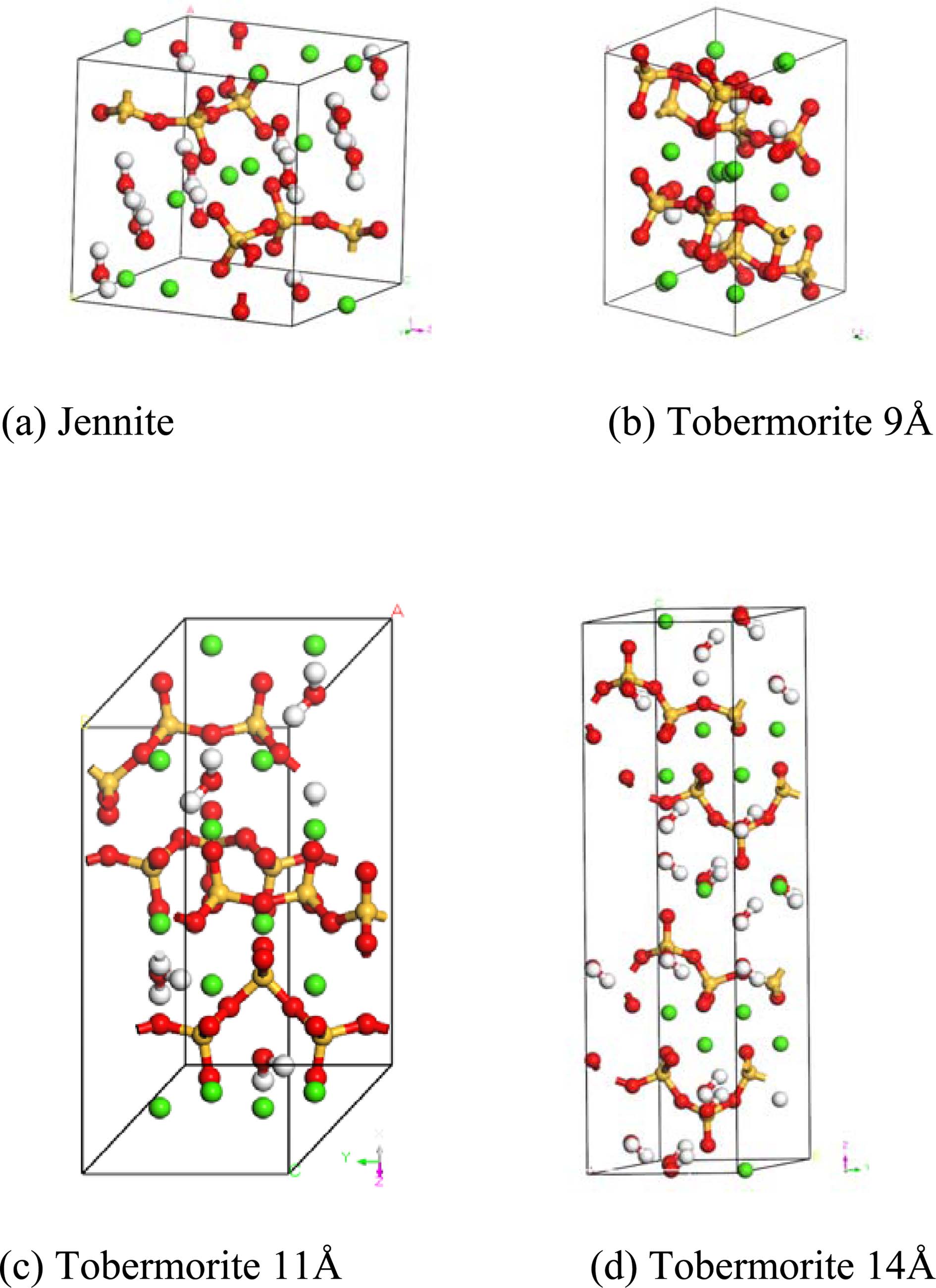
The construction of an initial MD model is of great importance to the MD simulations. According to the hypothesis proposed by Taylor [11], because the structures of Tobermorite 9Å, Tobermorite 11Å, Tobermorite 14Å, and Jennite are similar to C-S-H gel’s, these minerals can be considered as the replacements for the C-S-H gel in the construction of an initial MD model. Bonaccorsi [24-27] investigated the crystal structures of Tobermorite and Jennite, and gave the space group, lattice type, and cell parameters of Tobermorite (with interlayer spaces of 9Å, 11Å, and 14Å) and Jennite crystals as shown in Table 1. Fig. 1 shows the atomic structures of the monocrystals (Tobermorite 9Å, Tobermorite 11Å, Tobermorite 14Å and Jennite crystals) built based on Table 1.
The yellow balls represent silica atoms, the green balls represent calcium atoms, the red balls represent oxygen atoms, and the white balls represent hydrogen atoms.
|
Fig. 1 Molecular structures of C-S-H crystals’ initial models. |
The COMPASS (Condensed-phase Optimized Molecular Potential for Atomistic Simulation Studies) [29] force field are selected to describe the atomic interactions in the MD calculations. The COMPASS force field has been used in simulations of various types of materials, such as liquid, crystals, polymers, small organic molecules, inorganic materials, metal oxides, and silicon-aluminum silicates [7]. The expression of the COMPASS force field changes depending on the bonding interaction of the simulated objects. A general inorganic and covalent bonding system is used in this study. The parameter values used in the force field are drawn from the results of experimental investigations and calculations based on quantum mechanics. The reliability of the force field is thus considered to be considerably improved as compared with before [29].
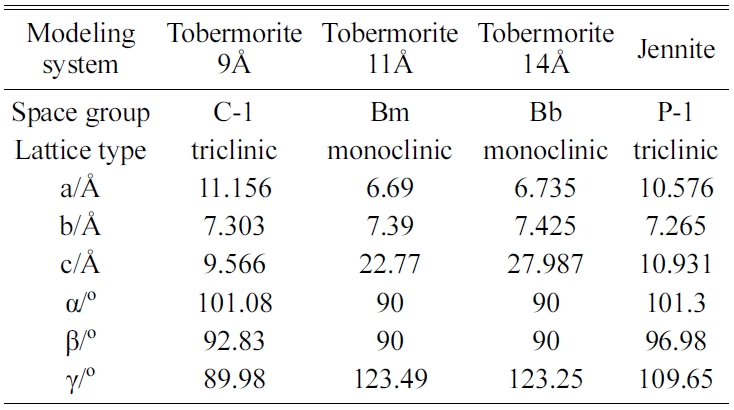
A COMPASS force field function generally consists of a bond term , Evalence an angle term Ecrossterm, and a non-bonding term Enon-bond The molecular total potential energy is Eotal = Evalence + Ecrossterm + Enon-bond. The bond term Evalence includes a bond stretching term, an angle bending term, a torsion angle term, an out-of-plane bending term, and an improper torsion term. The angle term Ecrossterm, includes a stretch-stretch term, a stretch-bend term, a stretch-torsion term, a bend-bend term, a torsion–torsion term, and a bend-torsion-bend term. The non-bonding term Evalence includes a van der Waals interaction term and an electrostatic term. The potential function is as follows [30]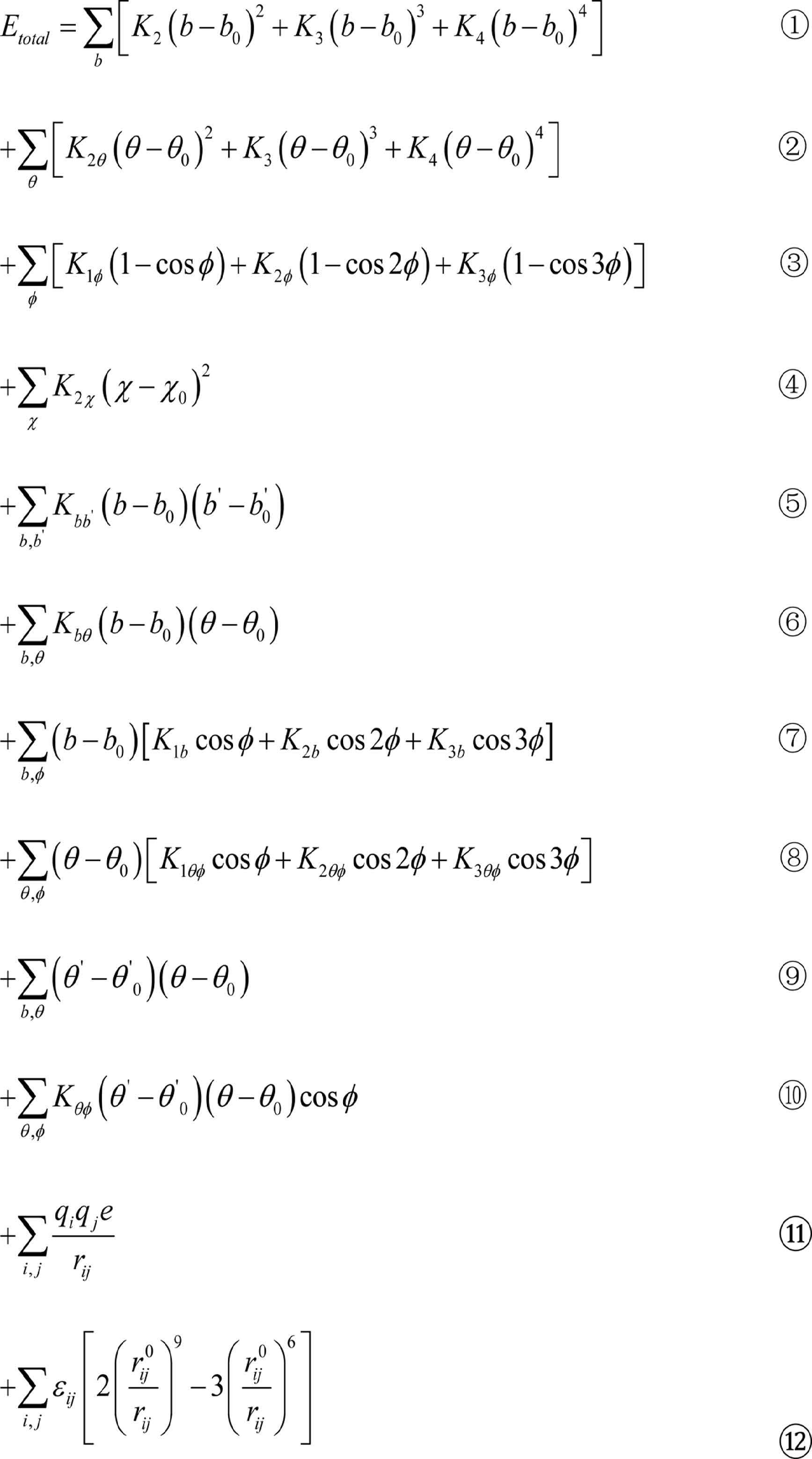
where items ①~⑫ are the stretch, angle bending, torsion angle, out-of-plane bending, stretch-stretch, stretch-bend term, stretch-torsion, stretch-bend, bend-bend, torsion-torsion, electrostatic, and van der Waals interaction terms, respectively.
The stretch and angle terms of the force field are expanded to the items of fourth power, and the complete cross interactions are maintained to ensure the accurate bonding interaction. This treatment is helpful in improving the simulation efficiency.
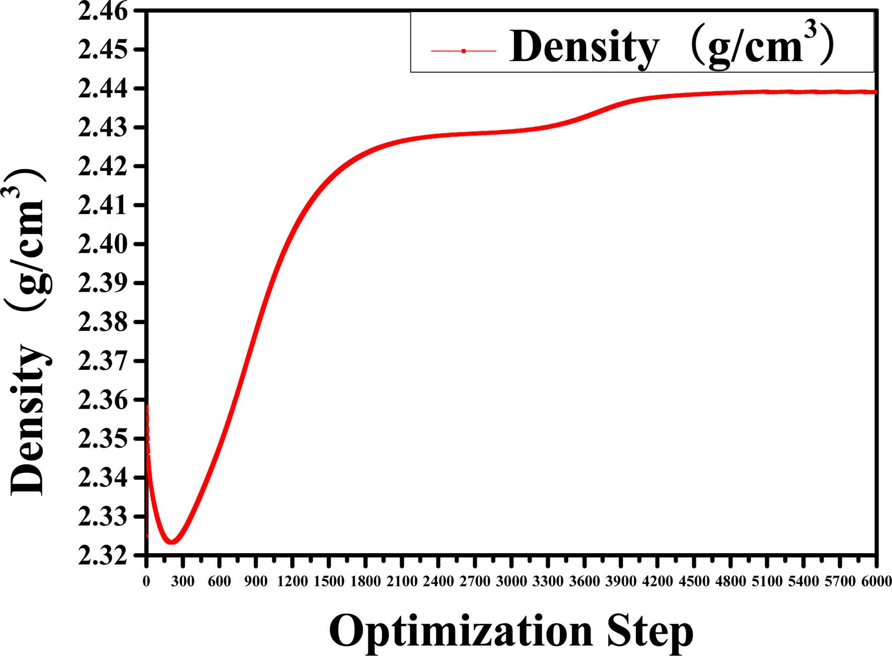
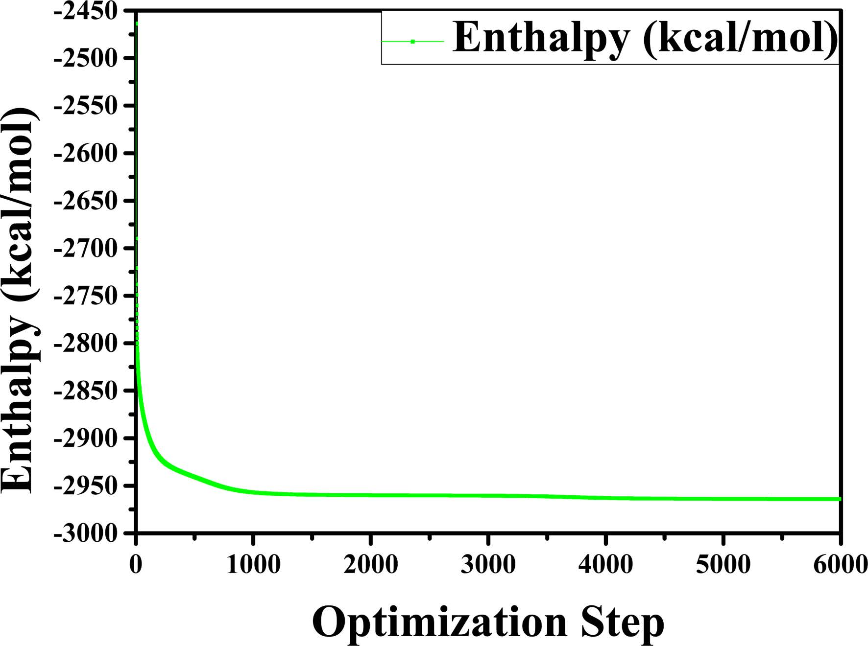
Before performing the MD simulations of the C-S-H gel, an energy minimization of the system is performed using an algorithm which combines the steepest descent, Quasi-Newton, and adjusted basis set Newton-Raphson (ABNR) method. The COMPASS force field and QEq electric charge method have been considered. The convergence of the analyses was verified by setting the threshold value of the total energy change equal to 1.0 × 10⁻⁷ kcal/mol. The number of simulation steps is 6,000. We have evaluated whether the system is balanced by observing the changes in energy and density during the optimization. The transient changes in density and relative energy of Jennite are shown in Fig. 2 and Fig. 3, respectively. As can be seen, the structural model tends to become stable when the number of optimizing steps reaches 5,000. Therefore, the crystal structure after 5,000 optimization steps was selected as the structure for the subsequent molecular dynamic relaxation. The optimized structures are used as the initial models for the subsequent MD simulations.
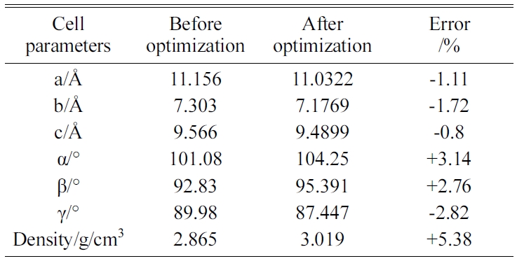
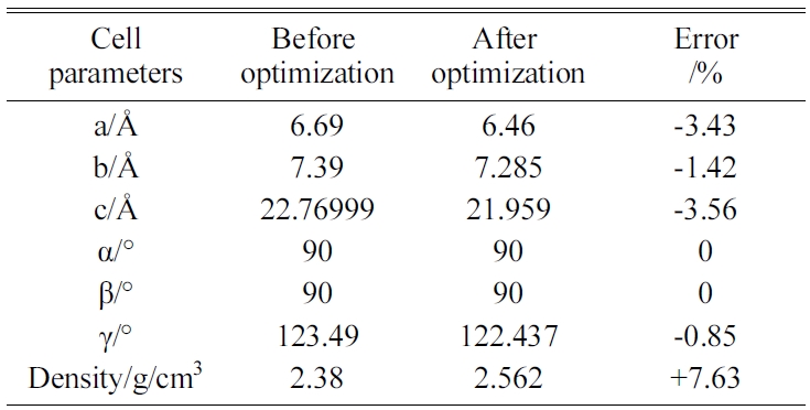
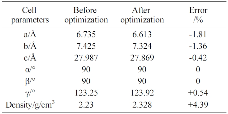
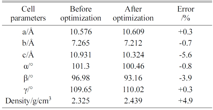
The energy minimization is also performed for Tobermorite 9Å, Tobermorite 11Å, and Tobermorite 14Å using the same optimization process. The cell parameters for Tobermorite 9Å, Tobermorite 11Å, Tobermorite 14Å, and Jennite crystals before and after optimization are listed in Tables 2-5, respectively. The crystal structures and cell parameters exhibit no obvious differences before and after optimization.
We have found that the cell parameters and crystal densities would change slightly (less than 5%) after optimizing the crystals’ structures using the COMPASS force field. There are no obvious changes in the silicon-oxygen tetrahedron structure within the cell, which confirms the suitability of this force field.
To verify our procedures, the mechanical properties of the geometrically optimized Jennite were calculated in the same way as that Hajilar and Shafei [10] used in studying the crystal structure of C-S-H. The structures after optimization have changed to some extent from the original ones by Hajilar and Shafei [10]. Tens of runs give the results with large fluctuations. For example, we obtained the results such as the set of K=66.09 GPa, G=32.27 GPa, E=83.27 GPa and v=0.29, and another set of K=70.21 GPa, G=35.62 GPa, E=91.39 GPa and v=0.28, which are almost in the same range as those reported in [10]. However, other values such as the set of K=103.49GP/a, G=49.06 GPa, E=127.0897 GPa and v=0.30, and another set of K=48.45 GPa, G=25.78 GPa, E=65.69 GPa and v=0.27 were also obtained. The fluctuations reflect the necessity of optimization procedure and selection of an appropriate approach.
Table 2 Table 3 Table 4
|
Fig. 2 Change in density of the structure for time step of 6000. |
|
Fig. 3 Change in relative energy of the structure for time step of 6000. |
|
Table 2 Cell parameters of Tobermorite 9Å’s initial structure before and after optimization. |
|
Table 3 Cell parameters of Tobermorite 11Å’s initial structure before and after optimization. |
|
Table 4 Cell parameters of Tobermorite 14Å’s initial structure before and after optimization. |
|
Table 5 Cell parameters of Jennite’s initial structure before and after optimization. |
 Following the geometry optimization, the MD simulations of the C-S-H are conducted in the canonical (NVT) [8, 10] and the isobaric-isothermal (NPT) [7-10, 21] ensembles. The temperature is set to 25 ℃ (298 K). The Nose-Hoover-Langevin (NHL) method is used for temperature control, while the Berendsen method is used for pressure control. The time step is 1.0 fs, and the total simulation time is 500 ps. From the computed atomic motion results, we calculate the bulk modulus and shear modulus of the C-S-H crystals using the constant-strain method after the MD simulation. The solutions obtained for the C-S-H crystals using the NVT and NPT ensembles differ by less than 3%.
Single-crystal materials typically exhibit anisotropy in their mechanical properties, whereas polycrystalline materials composed of single crystals are typically isotropic in their mechanical properties. Because the mechanical properties of single crystals do not represent the mechanical properties of polycrystalline materials well, we typically calculate the elastic constants of single crystals first and infer those of polycrystalline materials from them. Orthotropic materials have three orthogonal elastic symmetry planes, with the principal directions taken to be the directions of the coordinate axes.
The elastic properties of the C-S-H crystals at nano-scale are evaluated based on the interatomic bonds and force. The elastic stiffness coefficients, Cijkl, which relate the components of the stress, σij, and strain, εkl, tensors under a constant temperature T, are defined by formula (2):
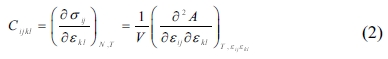
where V denotes the undeformed system volume, and is the Helmholtz free energy.
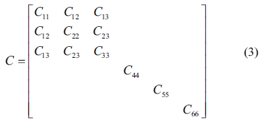
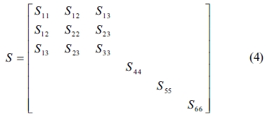
In this study, the elastic properties of the C-S-H crystals are computed by using the constant-strain method, in which a given strain is applied in a series of steps, the structure should be minimized after each step. We optimized the structures first to ensure that the input system has been minimized before the distorted structures are generated. The number specifying the distorted structures to be generated for each strain pattern was 4, and the maximum strain amplitude in each strain configuration was set to 0.003 to ensure that the deformations remain in the linear elastic regime. The elastic stiffness and compliance matrices of an orthotropic single crystal, denoted by C and S, respectively, are as follows
and
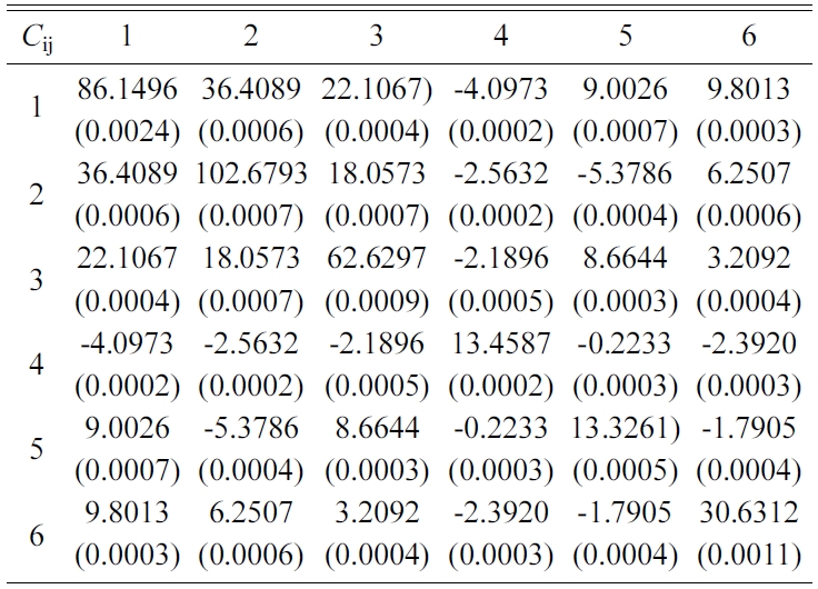
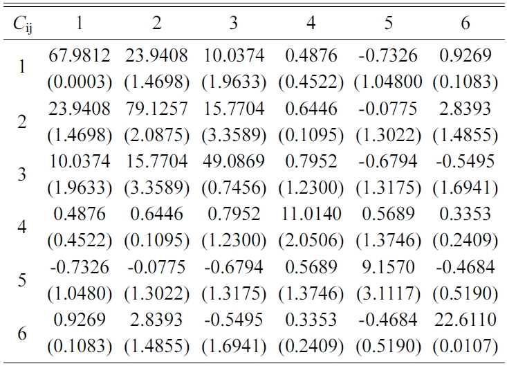
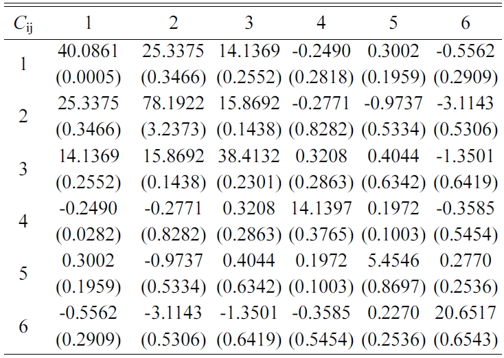
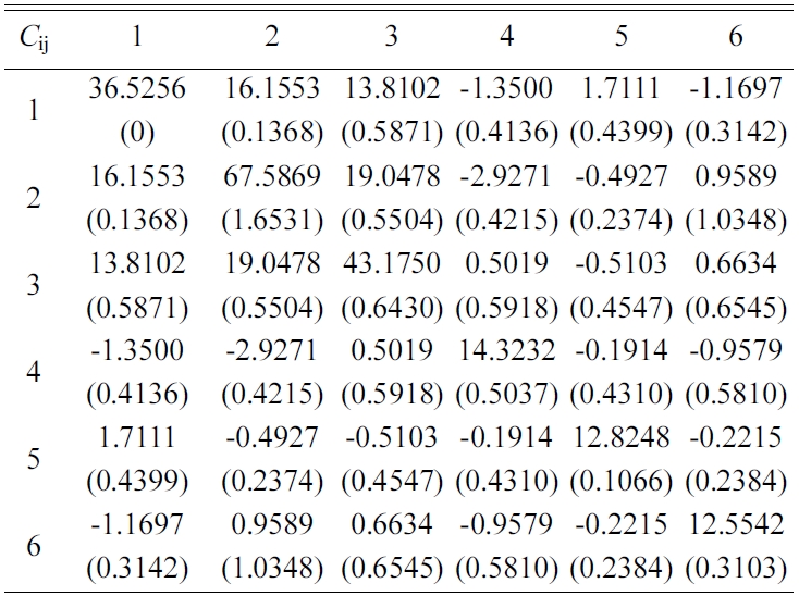
The elastic stiffness constants (the values of in formula (3)) of Tobermorite 9Å, Tobermorite 11Å, Tobermorite 14Å, and Jennite are shown in Table 6 through Table 9, in which the numbers in the parenthesis are the standard deviation.
The elastic stiffness constants listed in these tables are consistent with the orthotropy in most cases, except for a few values in Table 6. As shown in Table 1, the non-austere orthotropy of a crystal’s structural model might lead to this dispersion. Nevertheless, we treat the matrix as approximately orthotropic.
The single crystals’ elastic constants are used to estimate their polycrystalline ones. The maximum and minimum values of the bulk modulus and shear modulus are obtained as described by Voigt [32] and Reuss [33], respectively. Equations (5-8) are used to determine the polycrystalline elastic constants, based on the elastic stiffness and compliance matrices of the single crystals.

where the subscripts and represent the average values obtained as described by Voigt and Reuss, respectively.
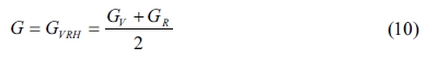
Hill [34] pointed out that the actual bulk and shear modulus are usually located between the values estimated as described by Voigt and Reuss. Therefore, the averages of the maximum and minimum values are considered to yield realistic estimates of the bulk and shear modulus, according to the widely used “Voigt-Reuss-Hill (VRH)” method as proposed by Hill and expressed by formulas 9 and 10:
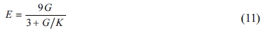
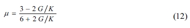
For isotropic materials, the Young’s modulus (E) and Poisson’s ratio (μ) of the crystals can be calculated from the bulk (K) and shear (G) modulus using formulas (11) and (12) as follows:
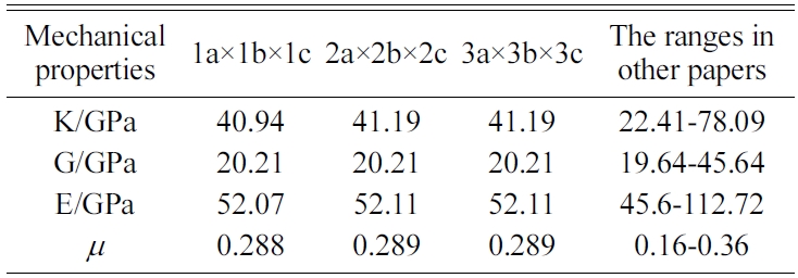
We expand a 1a × 1b × 1c single cell optimized into 2a × 2b × 2c, 3a × 3b × 3c, and 4a × 4b × 4c supercells to eliminate the influence of a size effect. We are then able to obtain the crystals’ elastic constants. We compare the results for the 4a × 4b × 4c structure of Jennite with those of its 3a × 3b × 3c structure and find that the error is less than 2%. The 4a × 4b × 4c structure is found to require substantial amounts of computing resources and time. Therefore, we do not perform the simulation of 4a × 4b × 4c structures in the subsequent computations.
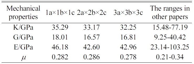
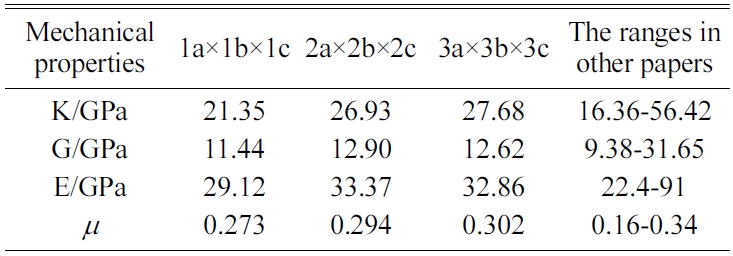
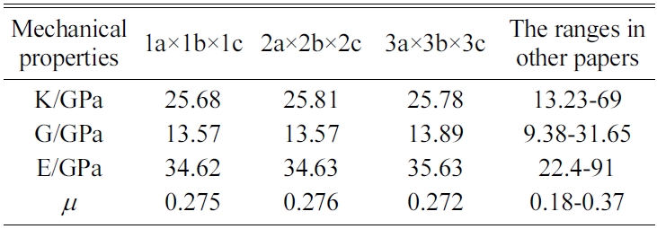
The MD results of the mechanical properties of Tobermorite 9Å, Tobermorite 11Å, Tobermorite 14Å, and Jennite crystals are summarized in Table 10 through Table 13. To verify the accuracy of estimates, the comparisons are made with the results provided by other studies: Pellenq [12, 13], Manzano et al. [16-18], Shahsavari et al.[19], Al-Ostaz et al. [7], Li et al. [8], Dharmawardhana et al. [9], Hajilar and Shafei [10], Rivas et al. [21], and Ji-kai Zhou et al. [29]. The ranges of these values are given in Table 10 through Table 13. From the tables, it can be seen that the results calculated in this study are located in reasonable ranges.
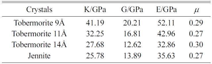
It appears that the mechanical properties of Tobermorite 9Å, Tobermorite 11Å, Tobermorite 14Å, and Jennite crystals are not sensitive to the number of cells. Therefore, the results for 3a × 3b × 3c structures are used in the subsequent computations, as shown in Table 14.
The C-S-H plays a major role in cement’s mechanical properties and durability, but its structure is still not clearly understood and needs to be studied further. Although the microstructure of the C-S-H is similar to those of Tobermorite and Jennite crystals, it is not as simple as those. Wu [35] and Shahasavari [19] introduced various methods for constructing the C-S-H models, including the Power-Brownyard model [36], the Feldmann-Sereda model [37], and the Jennings model [38-41]. Typically, the C-S-H models of different porosities are constructed based on Jennite and Tobermorite crystals, and they are arranged in a certain sequence. The mechanical properties of the C-S-H are then determined according to the accumulation pattern and density of these particles. In the widely used hybrid Jennings model [40], the C-S-H gel is considered to be a multiphase porous material with its components and pores distributed randomly. Based on the size, shape, type and distribution of the components, we can analyze the C-S-H composites using various homogeneous models. The self-consistent (SC) and Mori-Tanaka (MT) models have been demonstrated to be suitable for cement-based materials.
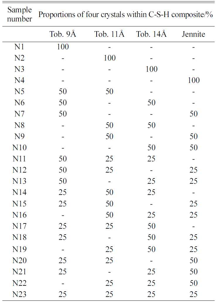
Since the mechanical properties of C-S-H directly depend on the proportions of Tobermorite 9Å, Tobermorite 11Å, Tobermorite 14Å, and Jennite crystals, 23 different proportions of the four crystals as shown in Table 15 are considered to assess the influence of the C-S-H crystals on the mechanical properties of the C-S-H composites.
Table 16
|
Table 16 Experimentally measured values of C-S-H’s Young’s modulus and Poisson’s ratio. |
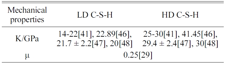
The porosities of 26% and 36% corresponding to high-density C-S-H (HD C-S-H) and low-density C-S-H (LD C-S-H), respectively, are considered according to Jennings [41]. Porosity needs to be taken into account because it has a huge influence on the mechanical properties of C-S-H. The C-S-H’s mechanical properties vary with the proportions of the four crystals in the C-S-H composite. Three methods are employed to derive the mechanical properties of the C-S-H composites, as described below.
The SC method can be used to estimate the mean elastic modulus of multiphase porous materials based on the mechanical properties of solid spherical particles [34, 42, 43]. The bulk and shear moduli of a composite consisting of two components can be obtained as follows:
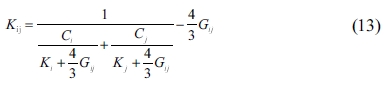
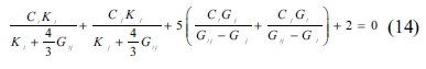
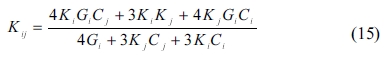
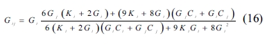
where Kij and Gij and are the composite’s bulk and shear modulus, respectively; Ki, Gi, Kj, and represent the two materials’ bulk and shear modulus; Ci and Cj are the proportions of the two components in the composite, respectively, in which i and j represent the crystals whose proportions are 50% each.
For a composite consisting of three components whose proportions are 25%, 25%, 50%, respectively, the bulk and shear modulus can be obtained in the following way: the two components of 25% proportions are considered firstly for the moduli calculated by Equations (13) and (14), and then the computed moduli are used to find the properties of the composite, in combination with the moduli of the component of proportion 50%. For a composite consisting of four components whose proportions are 25% each, the bulk and shear modulus can be obtained in a similar way that composing each two components first, and then composing the two composites. After considering the crystals’ proportions, the pores are treated as one component, and the bulk and shear moduli of the pores are zero when the porosities are taken into account. The mechanical properties obtained by this method are shown in Fig.4 through Fig. 7.
|
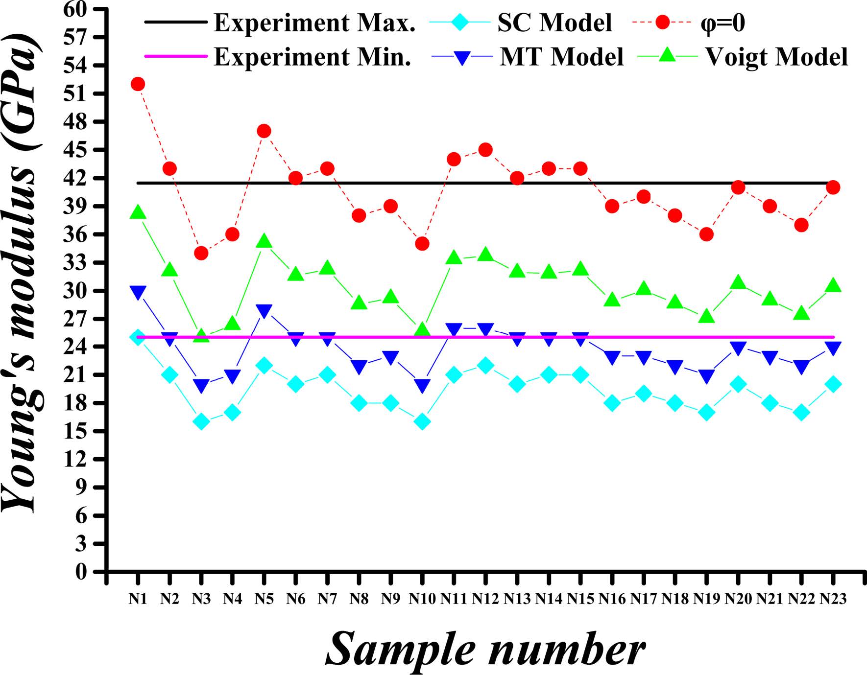
Fig. 4 Calculated versus experimental Young’s modulus values for porosity (j) of 26%. |
|
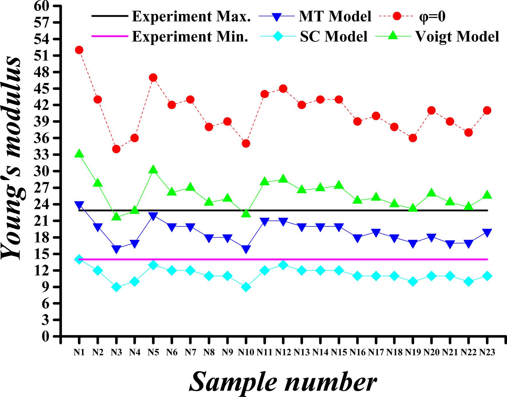
Fig. 5 Calculated versus experimental Young’s modulus values for porosity (j) of 36%. |
|
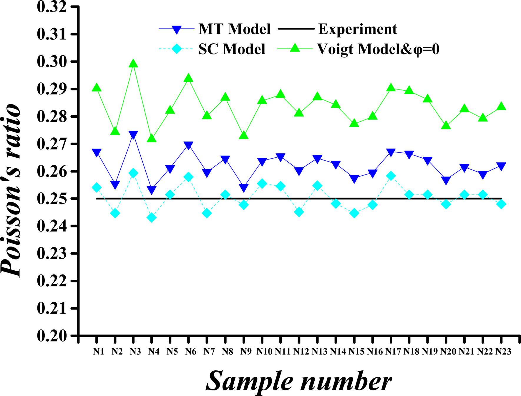
Fig. 6 Calculated versus experimental Poisson’s ratio values for porosity (j) of 26%. |
|
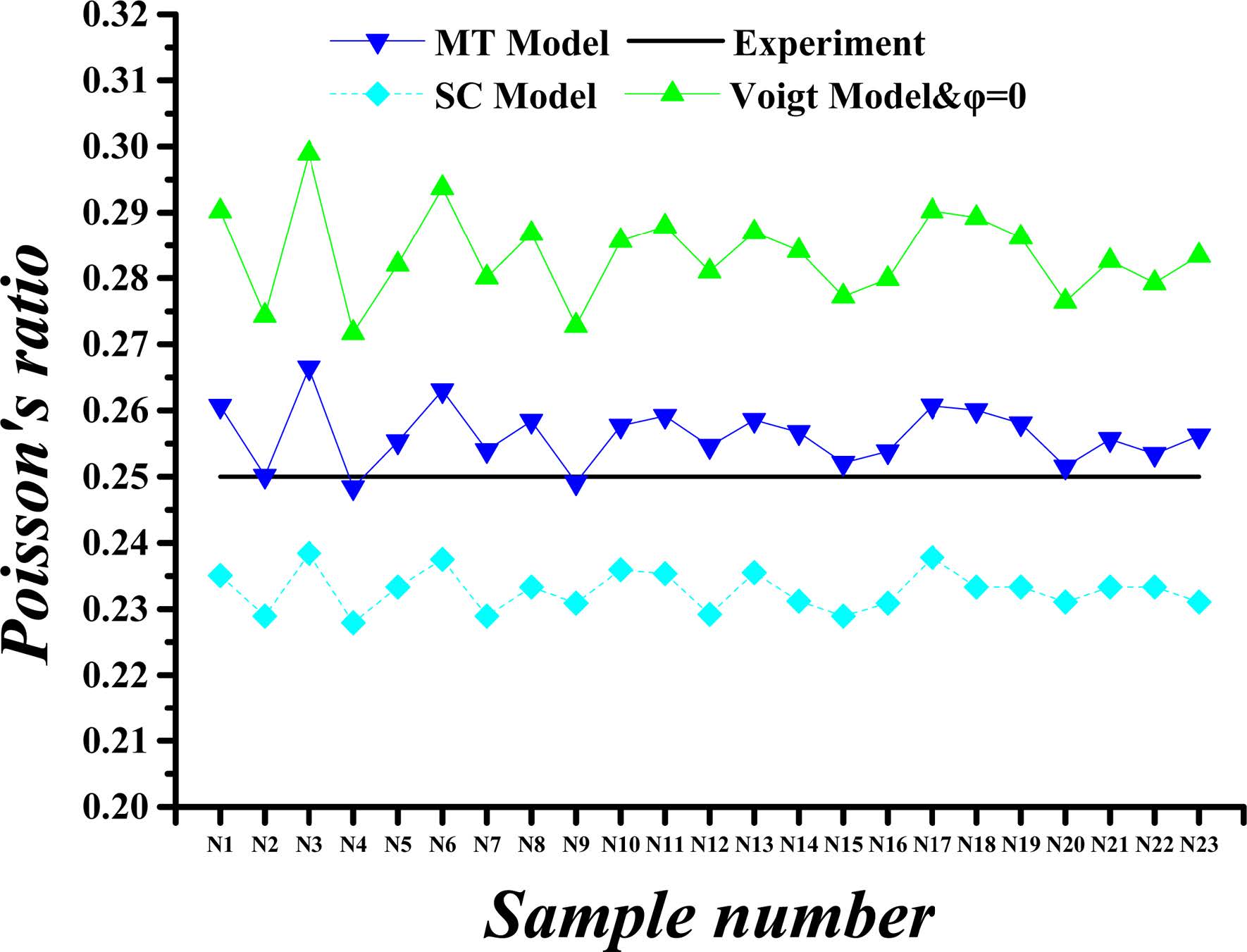
Fig. 7 Calculated versus experimental Poisson’s ratio values for porosity (j) of 36%. |
The MT method [44] was used to determine the back stress when studying the process of hardening in dispersion-hardening composites. The method is widely used in the study of non-homogeneous composites because it involves simple computations and takes the interaction of the composite’s inclusion into account. The bulk and shear modulus of a composite are obtained according to the MT method as follows:
where Kij and Gij are the composite’s bulk and shear modulus, respectively; Ki, Gi, Kj, and Gj represent the two components’ bulk and shear modulus, respectively; Ci and Cj and are the proportions of the two materials in the composite, in which i and j signify the crystals whose proportions are 50% each. For a composite with more than two components, the corresponding bulk and shear modulus can be determined in a similar way as in SC method. The mechanical properties obtained are shown in Fig. 4 through Fig. 7.
Voigt [45] proposed a hypothesis that the strains in all components in a composite are uniform before material failure occurs. By assuming that the component materials of the composite are isotropic, the effective bulk and shear modulus are computed as follows:
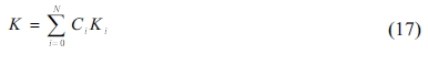
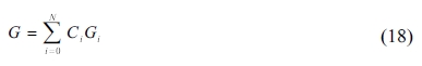
where Ki, Gi, and Ci are the bulk and shear modulus and the volume fraction of the ith material phase, respectively, and N represents the number of phases. The mechanical property values obtained by this method are shown in Fig. 4 through Fig. 7.
The results obtained using the SC, MT, and Voigt methods are compared with nano-indentation experiments conducted on the LD and HD C-S-H gel (e.g., [29, 41, 46-48]) to verify the accuracy of the MD simulation results. Experimentally measured values of the Young’s modulus and Poisson’s ratio of C-S-H as reported in the literature are shown in Table 16. Considering the fact that the mechanical properties reported by the listed studies are not necessarily consistent, their ranges are used for comparison purpose. Though a similar statement may not be entirely accurate for the Poisson’s ratio, it can be noticed that the percentage of difference the predicted Poisson’s ratio is minimal [10].
Fig. 4 through Fig. 7 show comparisons of the measured and calculated values of Young’s modulus and Poisson’s ratio for porosities (φ) of 26% and 36%.
The calculated and experimental values of the C-S-H’s Young’s modulus for the porosity of 26% and 36% are compared in Fig. 4 and Fig. 5, respectively. The Young’s moduli obtained by SC, MT and Voigt methods are almost the same when the porosity is 0%, whereas the values are greatly reduced when taking into account the porosity. The maximum value of Young’s modulus is obtained by using Voigt method. For the porosity of 26%, the Young’s modulus of different proportions of C-S-H crystals obtained by Voigt, MT and SC methods are approximately 74%, 59%, and 48% of the modulus at 0% porosity, respectively. For the porosity of 36%, the Young’s modulus obtained by Voigt, MT and SC methods are nearly 64%, 47%, and 36% of the modulus at 0% porosity, respectively.
The calculated and experimental values of the C-S-H’s Poisson’s ratio for a porosity of 26% and 36% are compared in Fig. 6 and Fig. 7. The Poisson’s ratios obtained in the ways described previously are equal when the porosity is 0%, whereas the values of Poisson’s ratios are slightly reduced when the porosity is taken into account, except for Voigt method. The maximum Poisson’s ratio is obtained by Voigt method. At the porosity of 26%, the Poisson’s ratios obtained by Voigt, MT and SC methods are approximately 100%, 93%, and 88%, respectively, of the Poisson’s ratio at 0% porosity. As the porosity is increased to 36%, the predicted Poisson’s ratios by Voigt, MT and SC methods are nearly 100%, 90%, and 82% of the value corresponding to 0% porosity, respectively.
In summary, the mechanical properties of C-S-H composites, specifically the Young’s modulus and Poisson's ratio, vary within certain ranges as the porosity and the component proportion change. For Young’s modulus of the HD C-S-H, the results obtained with Voigt method are found to be more closed to experimental results than those obtained with MT and SC method at each porosity level. As for the Young’s modulus of the LD C-S-H, the results obtained with MT method are found to be more closed to experimental results than those obtained with Voigt and SC method at each porosity level. For Poisson's ratio values, however, the results by SC method for HD C-S-H and those by MT method for LD C-S-H are closer to the experimental values. The Poisson's ratios and Young’s modulus as obtained with Voigt method are higher than those obtained with other methods. From the data we obtained, it can be seen that the results obtained with MT approach are closest to the experiment values, whereas the dispersion among the results obtained by the three methods is very small. Considering the experimentally measured values of C-S-H’s Young’s modulus and Poisson’s ratio disperse within a certain range, all Voigt, MT and SC methods are appropriate for C-S-H composite.
The Young’s modulus and Poisson's ratio of the C-S-H composite exhibit no strong relationships with those of the four crystals and do not vary with the changes in the component proportions. Because of the large differences in the Young’s modulus of the four crystals and the similarity of their Poisson's ratios, the Young’s modulus of the C-S-H composite changes substantially with the changes in the component proportions, whereas the Poisson's ratio of the C-S-H composite remains stable.
In this study, the MD models of the nanostructures of Tobermorite 9Å, Tobermorite 11Å, Tobermorite 14Å and Jennite crystals are established to evaluate the mechanical properties of the C-S-H composites with different porosities and component proportions. It is found that preprocessing and optimization of the initial structures are necessary to achieve stable and reliable results. The cell properties and crystal densities of the four types of crystals exhibit no obvious changes after optimization, and the inner structures remain stable. The cell structures of three sizes are examined to demonstrate the negligible effect of cell size. Using the SC, MT, and Voigt approaches, the mechanical properties of the C-S-H composites based on the four types of crystals are evaluated at low and high porosity, respectively.
The obtained results indicate that the Young’s modulus and Poisson's ratio of the C-S-H composites fluctuate within certain ranges with the changes in the porosity and component proportions. The Young’s modulus results as obtained by using the Voigt and MT methods are closer to experimental ones than those as obtained with the SC approach at each porosity level. However, the Poisson's ratio results as obtained with the SC method are closer to the experimental values for HD C-S-H, and the results as obtained by using the MT method are closer to the experimental ones for LD C-S-H. The highest values of Poisson's ratio and Young’s modulus are obtained by using the Voigt method, and the difference among the results obtained by the three methods is very small.
The findings reported here indicate that the proportions of four crystals in the C-S-H composites might be found through the comparisons between the experimental measurements and the MD calculations.
The authors gratefully acknowledge the financial support provided by the General Program of the National Natural Science Foundation of China (No.51478272), the International Cooperation and Exchange of the National Natural Science Foundation of China (51520105012), the Science and Technology Foundation for the Basic Research Plan of Shenzhen City (JCYJ2016042209 5146121), and the Collaborative Innovation Research Center for Environment-Friendly Materials and Structures in Civil Engineering, Southeast University.
- 1. N. Bouzoubaa, M.H. Zhang and V.M. Malhotra, Constr. Build. Mater. 31 (2001) 1393-1402.
-

- 2. J.S. Coutinho, Cem. Concr. Comp. 25 (2003) 51-59.
-
- 3. P.S. Song and S. Hwang, Constr. Build. Mater. 18 (2004) 669-673.
-
- 4. İ.B. Topçu and M. Canbaz, Constr. Build. Mater. 21 (2007) 1486-1491.
-
- 5. A.J. Allen, J.J. Thomas and H.M. Jennings, Nature materials. 6 (2007) 311-316.
-
- 6. X. Zhang, W. Chang, T. Zhang and K.O. Cong, J. Am. Ceram. Soc. 83 (2000) 2600-2604.
-
- 7. A. Al-Ostaz, W. Wu, H.D. Cheng and C.R. Song, Comp. Part B: Eng. 41 (2010) 543-549.
-
- 8. K. Li, Z.H. Shui and W. Dai, Mater. Res. Innov. 16 (2012) 338-344.
-
- 9. C.C. Dharmawardhana, A. Misra, S. Aryal, P. Rulis and W.Y. Ching, Cem. Concr. Res. 52 (2013) 123–130.
-
- 10. S. Hajilar and B. Shafei, Comp. Mater. Sci. 101 (2015) 216-226.
-
- 11. H.F.W. Taylor, J. Am. Ceram. Soc. 69 (1986) 464-467.
-
- 12. R. J-M. Pellenq, A. Kushima, R. Shahsavari, K.J.V. Vliet and M.J. Buehler, Proc. Natl. Acad. Sci. 106 (2009) 16102-16107.
-
- 13. R.J-M. Pellenq, N. Lequeux and H.V. Damme, Cem. Conre. Res. 38 (2008) 159-174.
-
- 14. D. Hou, Y. Zhu, Y. Lu and Z. Li, Mater. Chem. Phys. 146 (2014) 503-511.
-
- 15. X.F. Wang, T.R. Li, P. Wei, D.W. Li, N.X. Han, F. Xing, Y. Gan and Z. Chen, Comput. Mat. Sci. 146 (2018) 42-53.
-
- 16. H. Manzano, J.S. Dolado, A. Guerrero and A. Ayuela, Phys. Stat. Sol. (a) 204 (2007) 1775-1780.
-
- 17. H. Manzano, J.S. Dolado and A. Ayuela, Acta Mater. 57 (2009) 1666-1674.
-
- 18. H. Manzano, Proceedings Japan Soc. Civil Engineers. 661 (2009) 57-69.
- 19. R. Shahsavari, M.J. Buehler, J.M. Pellenq and F.J. Ulm, J. Am. Ceram. Soc. 92 (2009) 2323-2330.
-
- 20. D. Tunega and A. Zaoui, J. Comput. Chem. 32 (2011) 306-314.
-
- 21. J.S.M. Rivas, A. Mohamed, W. Hodo, R.V. Mohan and A. Rajendran, Int. J. Damage Mech. 25 (2015) 98-114.
-
- 22. Shahsavari, J.M. Pellenq and F.J. Ulm, Phys. Chem. Chem. Phys. 13 (2011) 1002-1011.
-
- 23. M.J.Q. Abdolhosseini, K.J. Krakowiak, M. Bauchy, K.L. Stewart and R. Shahsavari, Nat. Commun. 5 (2014) 1-10.
-
- 24. S. Merlino, E. Bonaccorsi and T. Armbruster, Eur. J. Mineral. 12 (2000) 411-429.
-
- 25. S.A. Hamid, Zeitschrift für Kristallographie. 154 (1981) 189-198.
-
- 26. E. Bonaccorsi, S. Merlino and A.R. Kampf, J. Am. Ceram. Soc. 88 (2005) 505-512.
-
- 27. E. Bonaccorsi, S. Merlino and H.F.W. Taylor, Cem. Concr. Res. 34 (2004) 1481-1488.
-
- 28. BIOVIA Materials Studio online help, Dassault Systèmes BIOVIA Co. San Diego, USA, 2016.
- 29. J.K. Zhou, J.K. Huang and C.H. Lin, Sci. Tec. Engrg. 15 (2015) 179-183.
-
- 30. H. Sun, J. Phys. Chem. B. 102 (1998) 7338-7364.
-
- 31. A. Al-Ostaz, G. Pal, P.R. Mantena and A. Cheng, J. Mater. Sci. 43 (2008) 164-173.
-
- 32. W. Voigt, Lehrbuch der Kristallphysik. Springer Fachmedien Wiesbaden, Germany, 1966.
-
- 33. A. Reuss, ZAMM-J. Appl. Math. Mech. 9 (1929) 49-58.
-
- 34. R. Hill, J. Mech. Phys. Solids. 13 (1965) 213-222.
-
- 35. W. Wu and C.Q. Yang, Polym. Degrad. Stab. 91 (2006) 2541-2548.
-
- 36. T.C. Powers and T.L. Brownyard, J. ACI. 18 (1947) 59-70.
- 37. R.F. Feldman and P.J. Sereda, Eng. J. 53 (1970) 53-59.
- 38. H.M. Jennings, Cem. Concr. Res. 30 (2000) 101-106.
-
- 39. P.D. Tennis and H.M Jennings, Cem. Concr. Res. 30 (2000) 855-863.
-
- 40. H.M. Jennings, Cem. Concr. Res. 38 (2008) 275-289.
-
- 41. H.M. Jennings, J.J. Thomas, J.S. Gevrenov, G. Constantinides and F.J. Ulm, Cem. Concr. Res. 37 (2007) 329-336.
-
- 42. A.V. Hershey, Art Univ. Calgary 21 (1954) 236-240.
- 43. K. Ekkehart, Z. Phys. 151 (1958) 504-518.
-
- 44. T. Mori and K. Tanaka, Acta Metall. 21 (1973) 571-574.
-
- 45. W. Voigt, Annalen Der Physik 274 (2006) 573-587.
-
- 46. P. Mondal, S.P. Shah and L. Marks, Cem. Concr. Res. 37 (2007) 1440-1444.
-
- 47. G. Constantinides and F.J. Ulm, Cem. Concr. Res. 34 (2004) 67-80.
-
- 48. P. Acker, Mater. Struct. 37 (2004) 237-243.
-
 This Article
-
2019; 20(S1): 19-30
Published on Jul 20, 2019
- Received on Dec 9, 2018
- Revised on Jan 11, 2019
- Accepted on Jan 11, 2019
Services
- Abstract
introduction
model formulation and simulation methods
conclusions
- Acknowledgements
- References
- Full Text PDF
Shared
Correspondence to
- Dawang Li a,*, Zhen Chen c,*
-
aGuangdong Provincial Key Laboratory of Durability for Marine Civil Engineering; College of Civil Engineering, Shenzhen University, Shenzhen, P.R. China
cDepartment of Civil and Environmental Engineering, University of Missouri, Columbia, MO 65211, USA
Tel : +86 -755 -2673-2835, +86 -755 -2653-4021
Fax: +86 -755 -2673-2835, +86 -755 -2653-4021 - E-mail: lidw@szu.edu.cn, chenzh@missouri.edu
Clean-Energy Research Institute(CRI), Hanyang University, 222, Wangsimni-ro, Seongdong-gu, Seoul, 04763, Korea
E-mail: jcpr@hanyang.ac.kr