


- Development of a new-type pile structure applicable to the pile-supported embankment
Il-Wha Leea, Su-Hyung Leeb, Gou-Moon Choia, Myungjae Leec and Mintaek Yooc,*
aAdvanced Infrastructure Research Team, Korea Railroad Research Institute, 176 Cheoldobangmulgwan-ro, Uiwang-si, Gyeonggi-do, 16105, Republic of Korea
bLight Rail Transit Research Team, Korea Railroad Research Institute, 176 Cheoldobangmulgwan-ro, Uiwang-si, Gyeonggi-do, 16105, Republic of Korea
cRailroad Structure Research Team, Korea Railroad Research Institute, 176 Cheoldobangmulgwan-ro, Uiwang-si, Gyeonggi-do, 16105, Republic of Korea
In this study, a new type of pile material with high economic efficiency and reliability for pile-supported embankment was developed using fly ash, blast furnace slag, and recycled aggregate, which are relatively low-cost industrial by-products. A series of strength experiments was conducted with the model piles fabricated using the developed new-type pile material to evaluate the design strength. As compressive strength of model pile decreases, the cost effectiveness also decreases. Based on test results, the specimen with a composition of 50% fly ash and 30% recycled aggregate was suggested as the most economical concrete material to meet requirement strength of 25 MPa for embankment piles. In addition, the applicability of the developed material was evaluated by numerically analyzing its physical properties in the embankment pile test section. From the numerical analysis results, we concluded the new-type cast-in-place pile material that utilizes industrial by-products can be used as an embankment pile material.
Keywords: New-Type pile, Pile-Supported Embankment, Fly ash, Blast furnace slag, Recycled aggregate
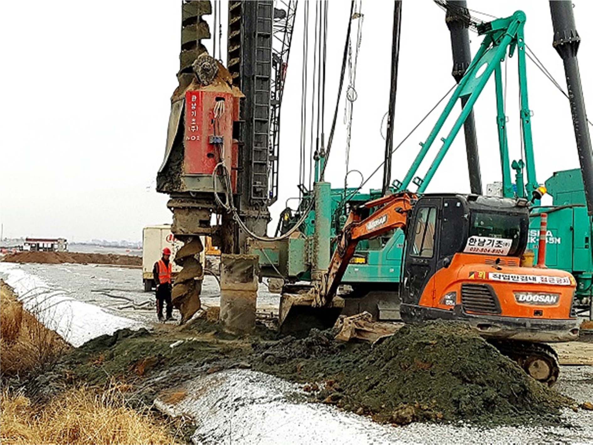
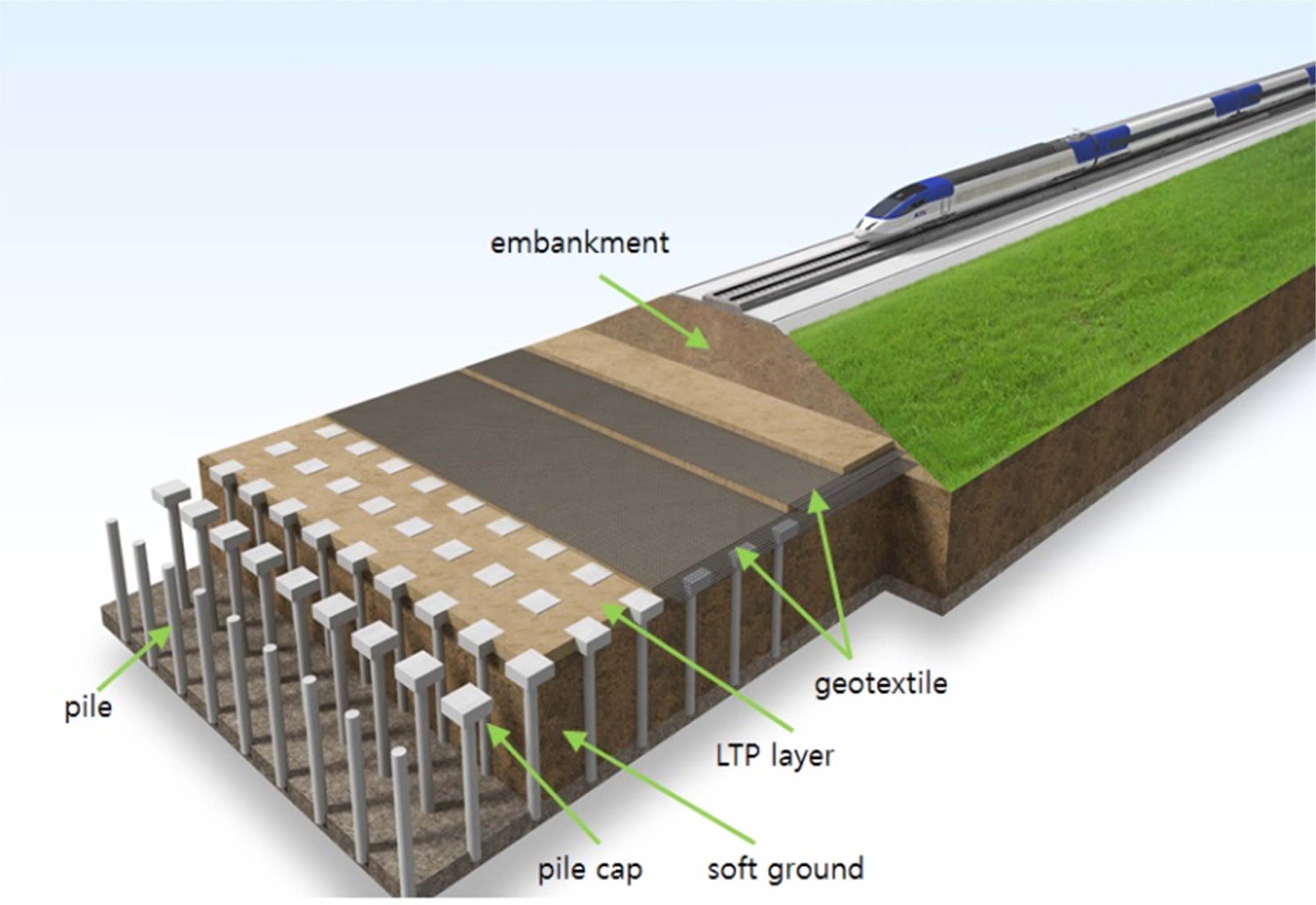
As the construction of roads and railways on soft soil has recently increased, demand for reinforcement methods to increase the safety of embankments and to suppress their settlement is increasing. In particular, in the case of the concrete high-speed railway track frequently used in the construction of railways in South Korea, it is essential to apply appropriate methods to address and control the settlement of soft soil because the allowable residual settlement is only 30 mm. The pile-supported embankment, one such settlement suppression method, can effectively suppress residual settlement in soft soil and thereby enable rapid railway construction. It has been applied to diverse railway construction projects in China and Europe as an effective countermeasure against soft soil settlement [1-2]. The pile-supported embankment was also applied to railway structure in Korea as shown in Fig. 1. The method installs piles at regular intervals in a soft soil layer to generate shear resistance with relatively small supporting stiffness, thereby forming arching structures in an embankment. These arching structures formed between piles reduce the vertical stress acting on soft soil and increase the vertical stress transmitted to the piles [3-7]. In addition, a recent research assessed the safety and economic feasibility of the Pile-Supported Embankment Method applied to the railway structure (Fig. 2) through a variety of examples where the Pile-Supported Embankment is applied [8].
In general, these embankment piles for settlement suppression share a relatively small load compared to the load applied to the pile foundation. If the pile materials applied to the foundation of bridges and buildings are applied as they are, there is a possibility of over-specification of the design in terms of the pile materials. Therefore, it is necessary to develop economical pile materials that can meet the purpose of the embankment pile structure and secure bearing capacity.
As such, in this study, a new type of pile material with high economic efficiency and reliability was developed using fly ash, blast furnace slag, and recycled aggregate, which are relatively low-cost industrial by-products. A series of strength experiments was conducted with the model piles fabricated using the developed new-type pile material to evaluate the design strength. In addition, the applicability of the developed material was evaluated by numerically analyzing its physical properties in the embankment pile test section.
|
Fig. 1 Pile-supported embankment construction site. |
|
Fig. 2 Pile-supported embankment. |
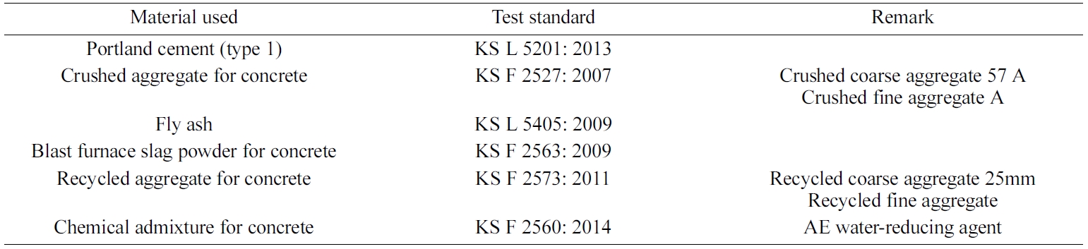
To select economical embankment pile materials suitable for replacement of the existing high-strength pile foundation, a material test was conducted to replace a certain percentage of the materials constituting the existing concrete piles with relatively low-cost industrial by-products. Fly ash and blast furnace slag were used as a binder instead of cement, and recycled aggregate was used instead of natural aggregate as a filler. Strength experiments were performed by varying the percentage of replacement. The target design strength was set, with consideration of the load acting on an embankment pile, to 18 MPa. The quality of each material used in fabricating the specimens for indoor tests was examined in accordance with the approved test methods listed in Table 1.
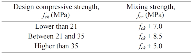
The concrete mixing process involves the determination of both the standard deviation and the required average strength, as well as the selection, through test mixing, of appropriate mixing ratios to achieve the average strength. The average strength of the selected mixing ratios must be higher than the design compressive strength by the amount specified in the [9], considering standard deviation. The standards suggest the application of the mixing strengths given in Table 2 if there is no field strength record for the calculation of standard deviation. As such, a mixing strength of 25 MPa was determined to be appropriate and achieved by the addition of 7 MPa to the target design strength of 18 MPa.
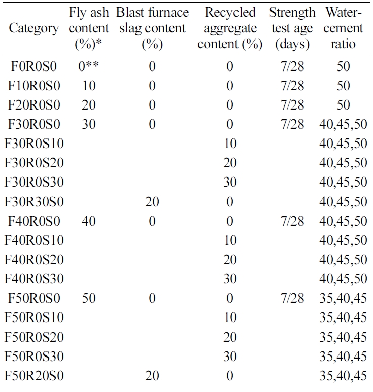
Strength tests were conducted according to the content change to determine the optimal proportions of fly ash, blast furnace slag, and recycled aggregate. First, the fly ash content was varied from 0% to 50% by intervals of 10%. In addition, when the fly ash contents were 30% and 50%, recycled aggregate was added at proportions of 10%, 20%, and 30%, and blast furnace slag was added at a proportion of 20%. Table 3 summarizes the experimental plan.
In the case of the fly ash content test, the strength of the concrete was found to be closely related to the water/binder ratio, and the compressive strength showed a tendency to decrease as the ratio increases. Fig. 3 shows the compressive strength test results of the concrete specimens according to the fly ash content under the same water/binder ratio conditions. At relatively low water/binder ratios of 40% and 45%, the strength of the concrete showed a clear tendency to decrease as the fly ash content increased. As the water/binder ratio increased to 50%, however, there was no consistent tendency between the fly ash content and the concrete strength.
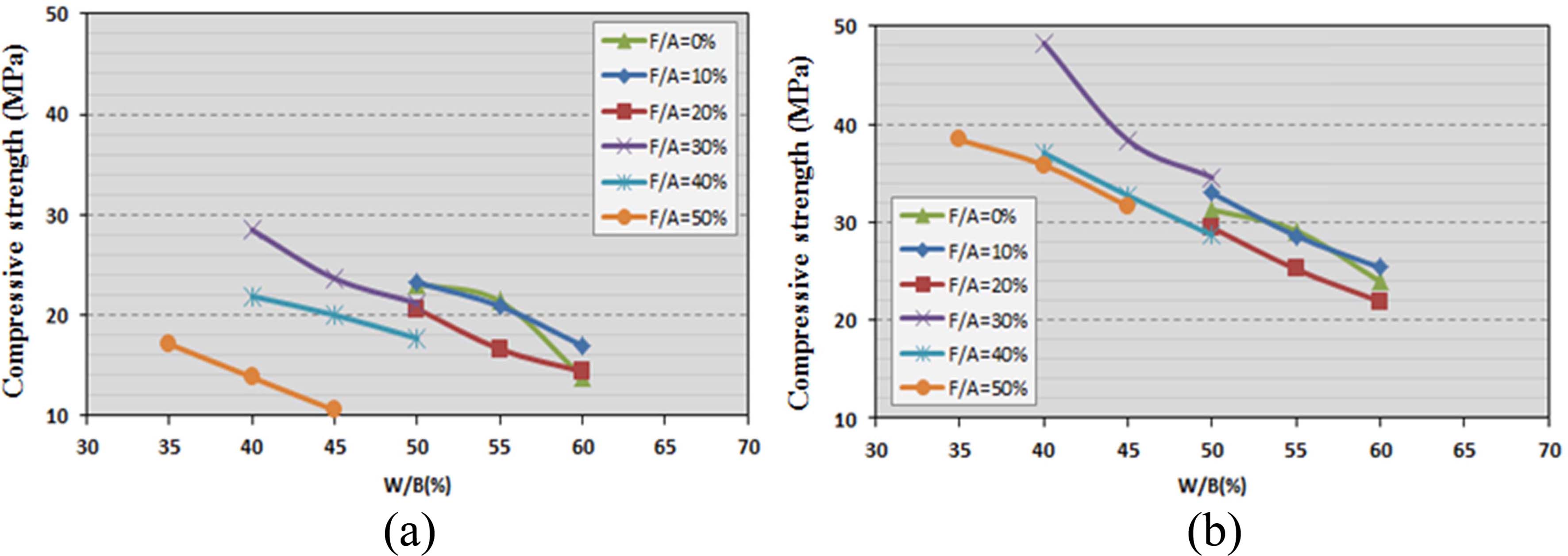
The fly ash content test results are summarized with water/binder ratio as shown in Fig. 4, the general tendency by which the strength decreases as the water/binder ratio increases can be confirmed. Overall, the compressive strength curve moved downwards as the fly ash content increased. This tendency was more obvious for the strength at 7 days of age than for the strength at 28 days.
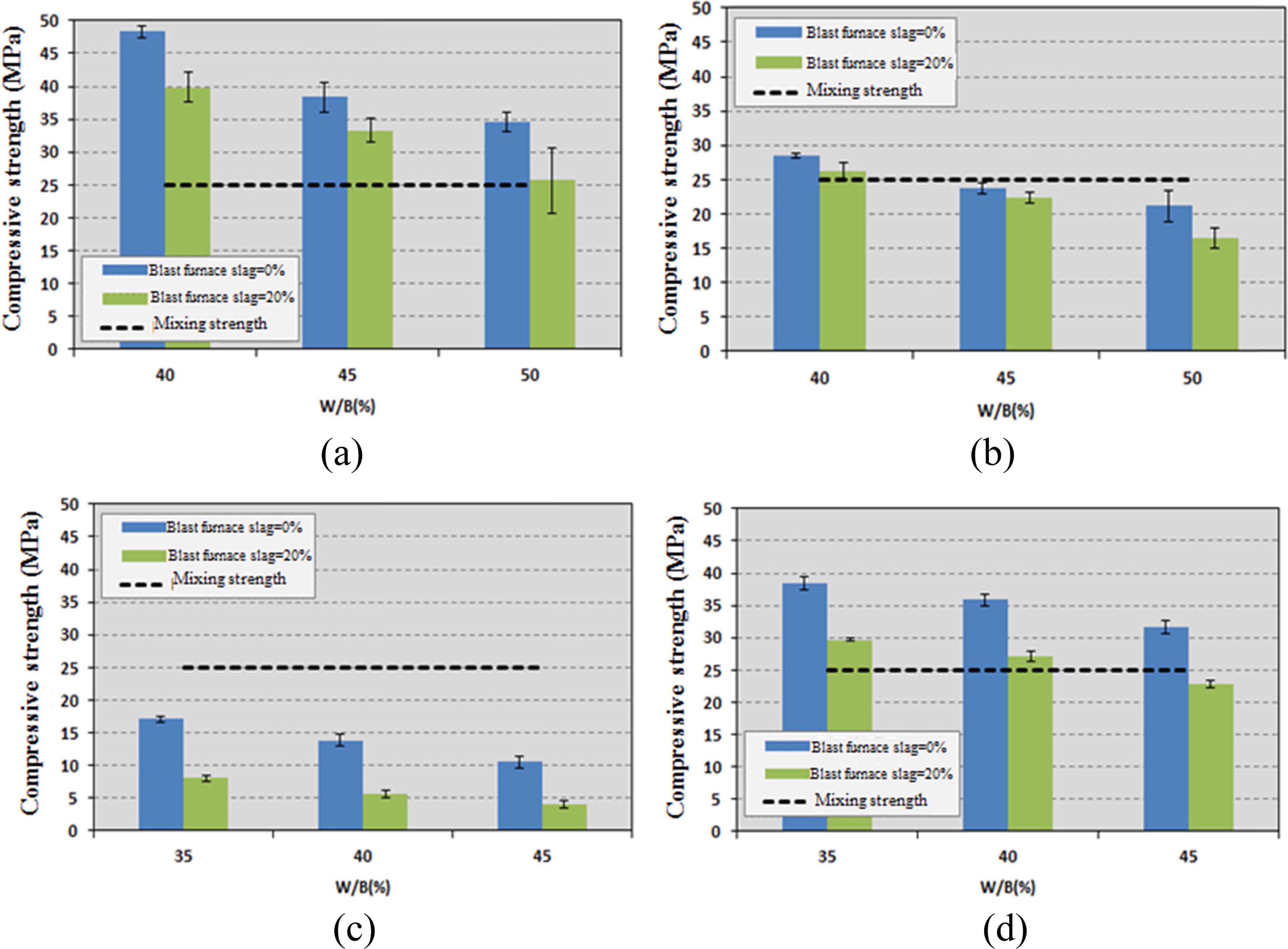
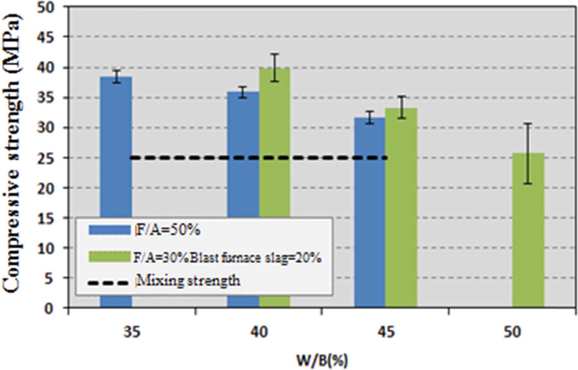
As shown in Fig. 5, when blast furnace slag was added during concrete mixing, the strengths at both 7 and 28 days of age decreased. This tendency occurred consistently when the fly ash contents were 30% and 50%. When the 20% blast furnace slag content was added to the 50% fly ash content, the strength at 28 days of age could not retain the intended mixing strength of 25 MPa at a water/binder ratio of 45%; however, the mixing strength was met in the other tests.
To compare the contents of the experimental materials as cement substitutes under the same conditions, the compressive strength of the case with the 50% fly ash content was compared with that of the case with 30% fly ash and 20% blast furnace slag. Fig. 6 shows that cement replacement with a combination of fly ash and blast furnace slag delivered significantly better compressive strength than replacement with just fly ash under the same water/binder ratio condition.
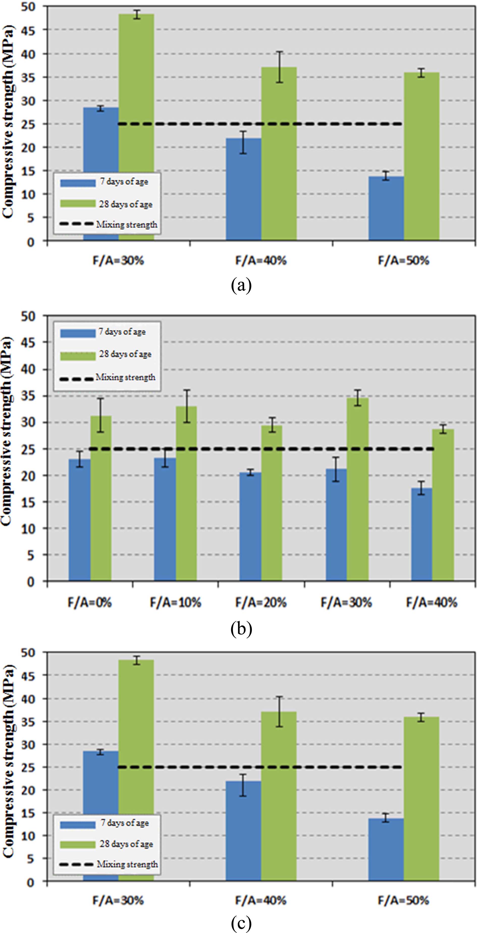
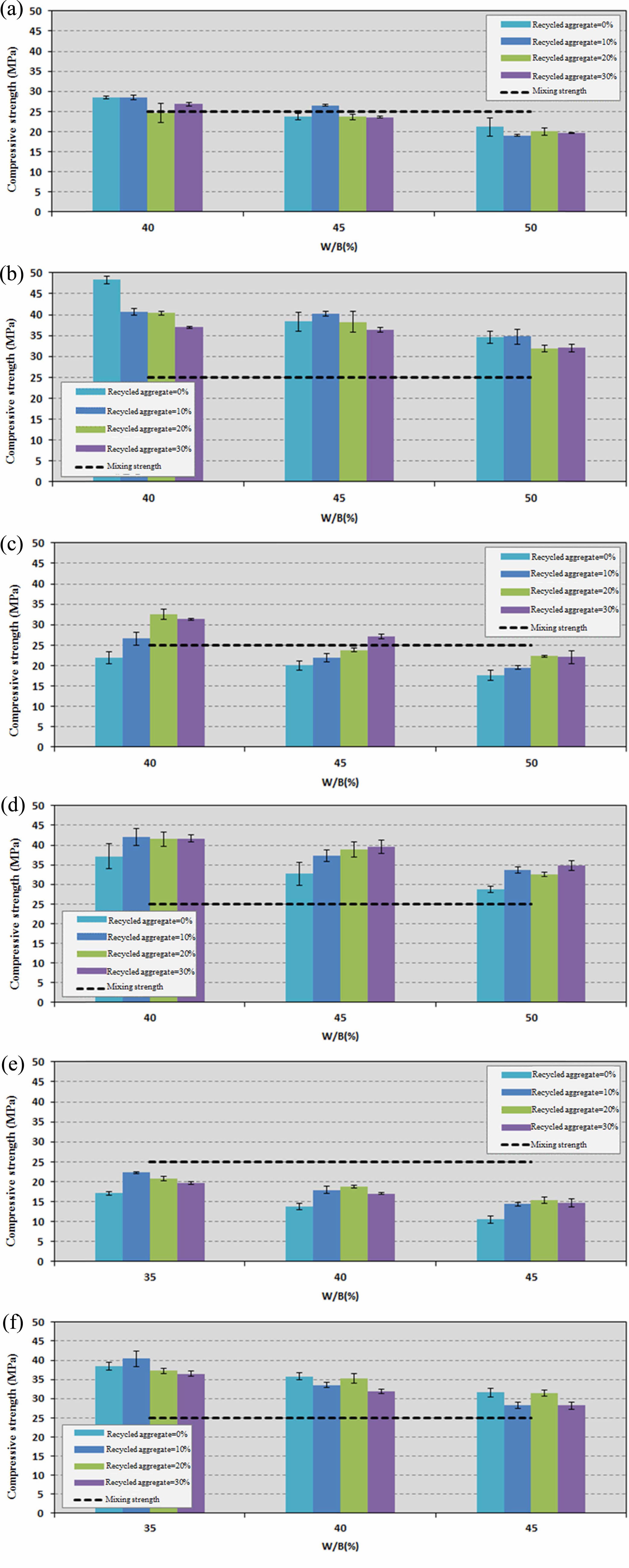
Fig. 7 shows the compressive strength results when recycled aggregate was used to replace natural aggregate during concrete mixing. The test results showed that the strength tended to decrease as the recycled aggregate content increased when the fly ash contents were 30% and 50%. The strength at 28 days of age, did, however, meet the mixing strength requirement of 25 MPa with the recycled aggregate content at 30%.
|
Fig. 3 Concrete strength according to the fly ash content. (Stage 1): a) water/binder ratio (W/B)=40%, b) water/binder ratio (W/B)=45% and c) water/binder ratio (W/B)=50%. |
|
Fig. 4 Fly ash content test results. (Stage 2): a) Strength at 7 days of age and b) Strength at 28 days of age. |
|
Fig. 5 Blast furnace slag addition test results. (Stage 3): (a) fly ash content 30% (strength at 7 days), b) fly ash content 30% (strength at 28 days), c) fly ash content 50% (strength at 7 days) and d) fly as content 50% (strength at 28 days). |
|
Fig. 6 Concrete strength comparison under the 50% cement replacement condition. |
|
Fig. 7 Compressive strength test results according to the recycled aggregate content. (Stage 4): a) fly ash content 30% (strength at 7 days), b) fly ash content 30% (strength at 28 days), c) fly ash content 40% (strength at 7 days), d) fly ash content 40% (strength at 28 days), e) fly ash content 50% (strength at 7 days) and (f) fly ash content 50% (strength at 28 days). |
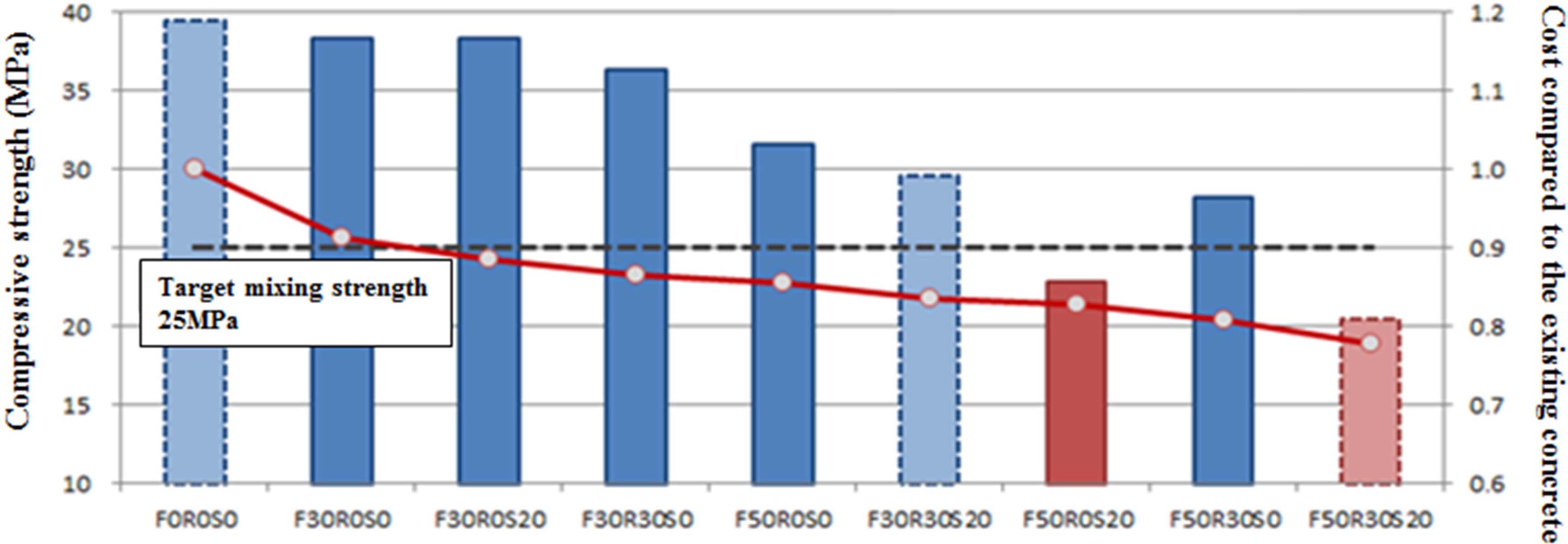
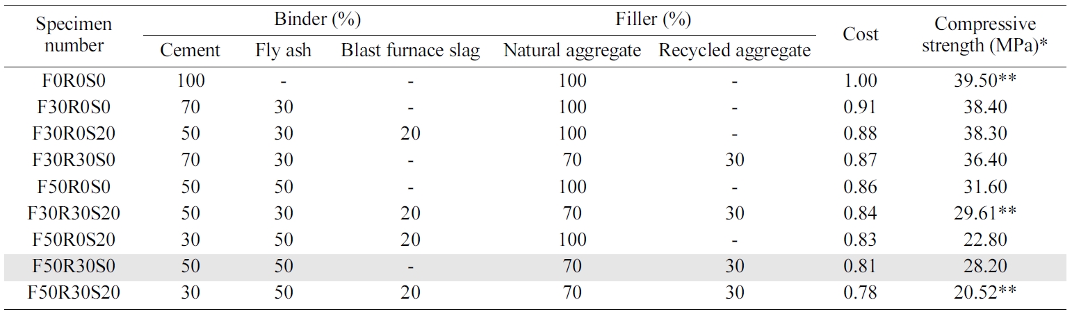
Compressive strength testing of the mixed concrete material created using industrial by-products for the development of an economical concrete pile material indicated that the strength at 28 days of age showed a tendency to decrease as the contents of fly ash, blast furnace slag, and recycled aggregate increased. It was found that mixing fly ash and blast furnace slag as cement substitutes was more beneficial in terms of the compressive strength than using fly ash alone. Moreover, when the industrial by-products replaced more than 50% of cement content, the 25 MPa mixing strength requirement could not be met. According to [10], concrete is composed of approximately 67.9% fillers and 11.1% binders. When it comes to the proportions in the concrete production cost, however, binders represent 52.6% and aggregates, which are fillers, 43.4%. Based on these proportions, economic efficiency of concrete composition can be summarized as given in Table 4.
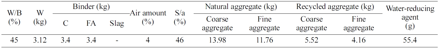
Fig. 8 provides a visual depiction of the data in Table 4. X-axis on left sides means the compressive strength and X-axis on right sides means the cost effectiveness. As compressive strength decreases, the cost effectiveness also decreases. As a results, the F50R30S0 specimen with a composition of 50% fly ash and 30% recycled aggregate was the most economical concrete material to meet the mixing strength requirement of 25 MPa for embankment piles. This represents an effective cost-savings of approximately 19% compared to the cost of existing cast-in-place concrete. Table 5 gives the most economical optimal mixing ratio results that still meet the mixing strength requirement.
|
Fig. 8 Concrete compressive strength test and cost analysis results. |
|
Table 4 Economic efficiency analysis for concrete pile utilizing industrial by-products. |
|
Table 5 Economic efficiency analysis for concrete pile utilizing industrial by-products. |
To evaluate the compressive strength of the pile with the proposed final mixing ratio, an experiment was performed on the compressive strength using concrete specimens. For the experiment, 21 cylindrical model piles with a size of φ400×1400 mm were fabricated in accordance with [11], and cured under the same conditions as those for the specimens.
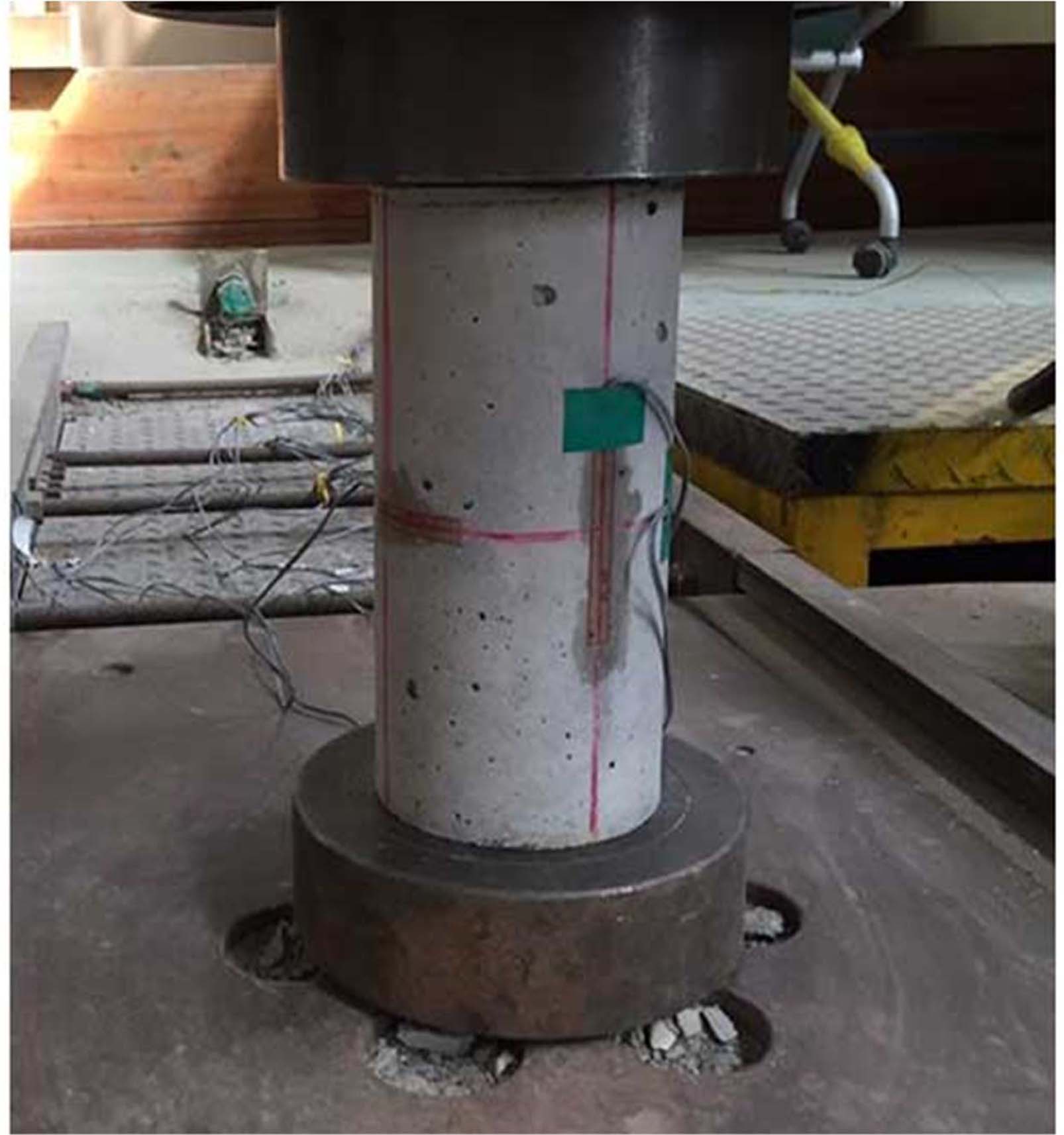
The concrete compressive strength test was conducted after the same curing period as that for the bending and shear tests of the model piles. A 1,000-kn-class UTM was used as the compressive strength test equipment in accordance with [12], as shown in Fig. 9.
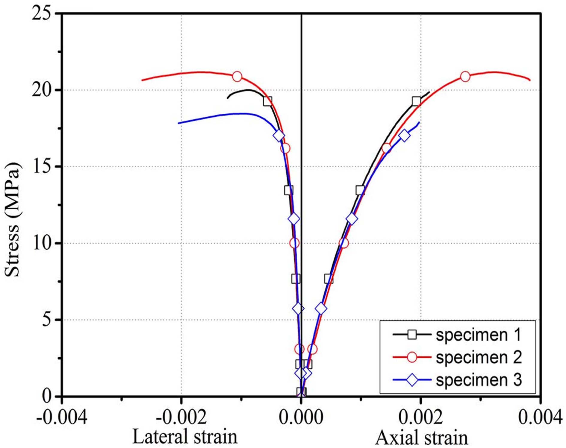
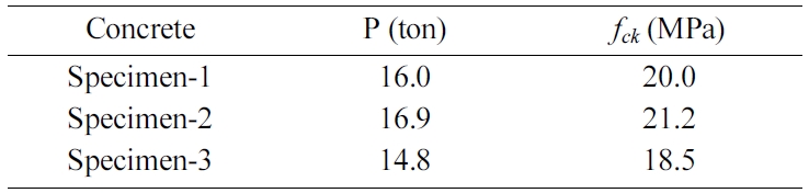
Fig. 11 and Table 6 both reflect the results of the compressive strength test of the model piles. Fig. 11 shows the stress-strain graph of the concrete measured by the strain gauges in the longitudinal and transverse directions attached to the model piles. Table 6 lists the finally obtained compressive strengths of the model piles. As shown in the table, the compressive strengths of the concrete model piles ranged from 18.5 to 21.2 MPa with an average of 19.4 MPa. Their strengths exceeded the embankment pile material target design strength of 18 MPa.
|
Fig. 9 Concrete compressive strength test. |
|
Fig. 10 Stress-strain graph of the model piles. |
|
Fig. 11 Test section for evaluating bending performance. |
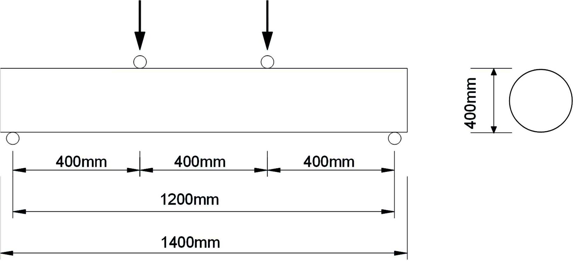
To evaluate the bending strengths of the experimental embankment concrete piles that utilized industrial by-products, the [13] method was applied and the same model piles were used as those used for the compressive strength test. The test section was a simply supported beam, as shown in Fig. 10, and the four-point loading method was applied. The distance between the reaction force points was 1,200 mm, and the distance between the loading points was 400 mm.
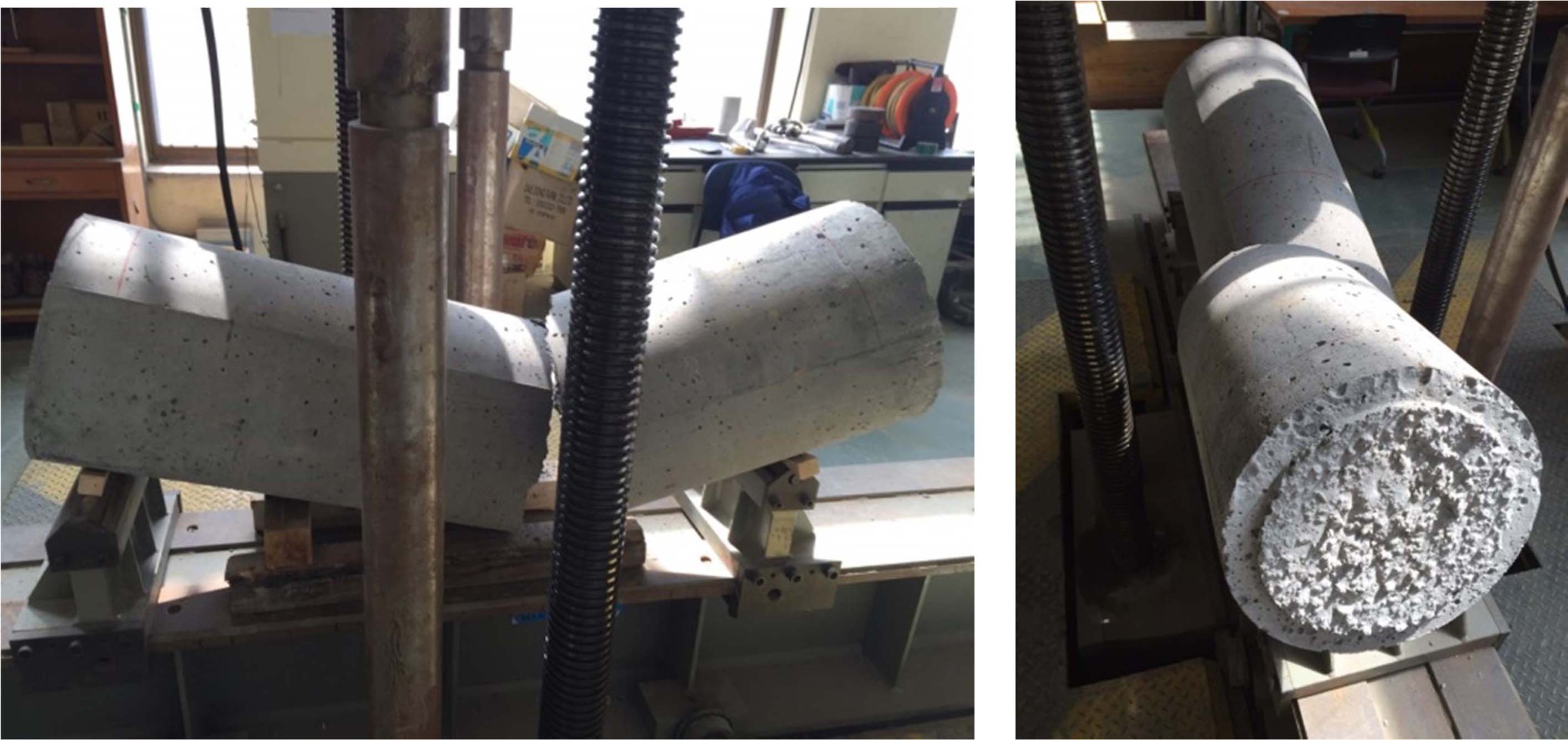
As for the failure pattern of the model piles, cracks occurred at the failure induction section between the loading points. Failure occurred almost simultaneously with crack occurrence (Fig. 12).
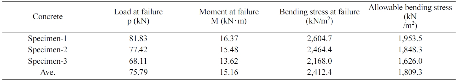
Table 7 lists the results of the bending strength test of the model piles. As indicated in the table, bending failure occurred in the load range between 68.11 and 81.83 kN for the embankment concrete piles that utilized industrial by-products, with the average bending failure occurring at 75.79 kN. The load range can be converted into a moment range between 13.62 and 16.37 kN‧m considering the distances between the points. The bending stress at failure was the bending strength by the pure bending moment in a state where the axial stress was not applied. The bending strengths of the model piles were found to be between 2.17 and 2.60 MPa from the moment and section modulus at failure, and the average was 2.41 MPa. The allowable bending stress was determined by applying a strength sensitivity coefficient of 0.75, and the determined average allowable bending stress was 1.81 MPa.
|
Fig. 12 Model pile failure image during the bending strength test. |
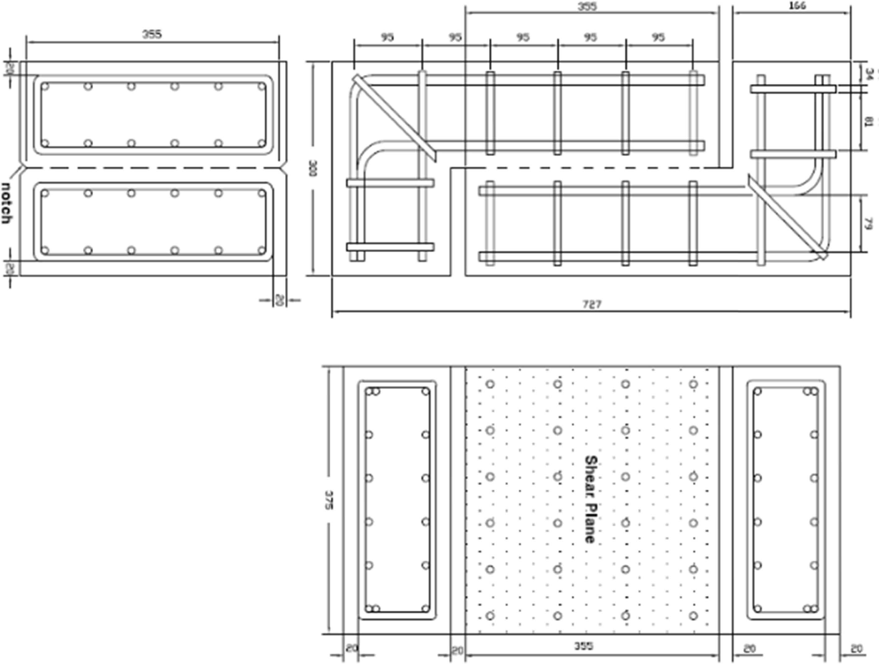
To evaluate the shear strengths of the embankment concrete piles that utilized industrial by-products, the shear strength test method of [14], which used steel to reinforce the non-test section and induce a shear failure surface by placing a notch, was applied. A total of three specimens, 300 mm x 375 mm x 727 mm, were fabricated as shown in Fig. 13. The shear test section was planned to be 355 mm in height and 325 mm in width.
The same UTM as that for the previous tests was used to apply loads on the specimens. A uniaxial compressive load was applied to generate a 0.0017 mm displacement per second, and it was continuously increased until the specimen failed. The relative displacement of the experimental section caused by the load change was measured by installing four linear variable differential transformers (LVDTs) at the top, bottom, and on both sides of each specimen.
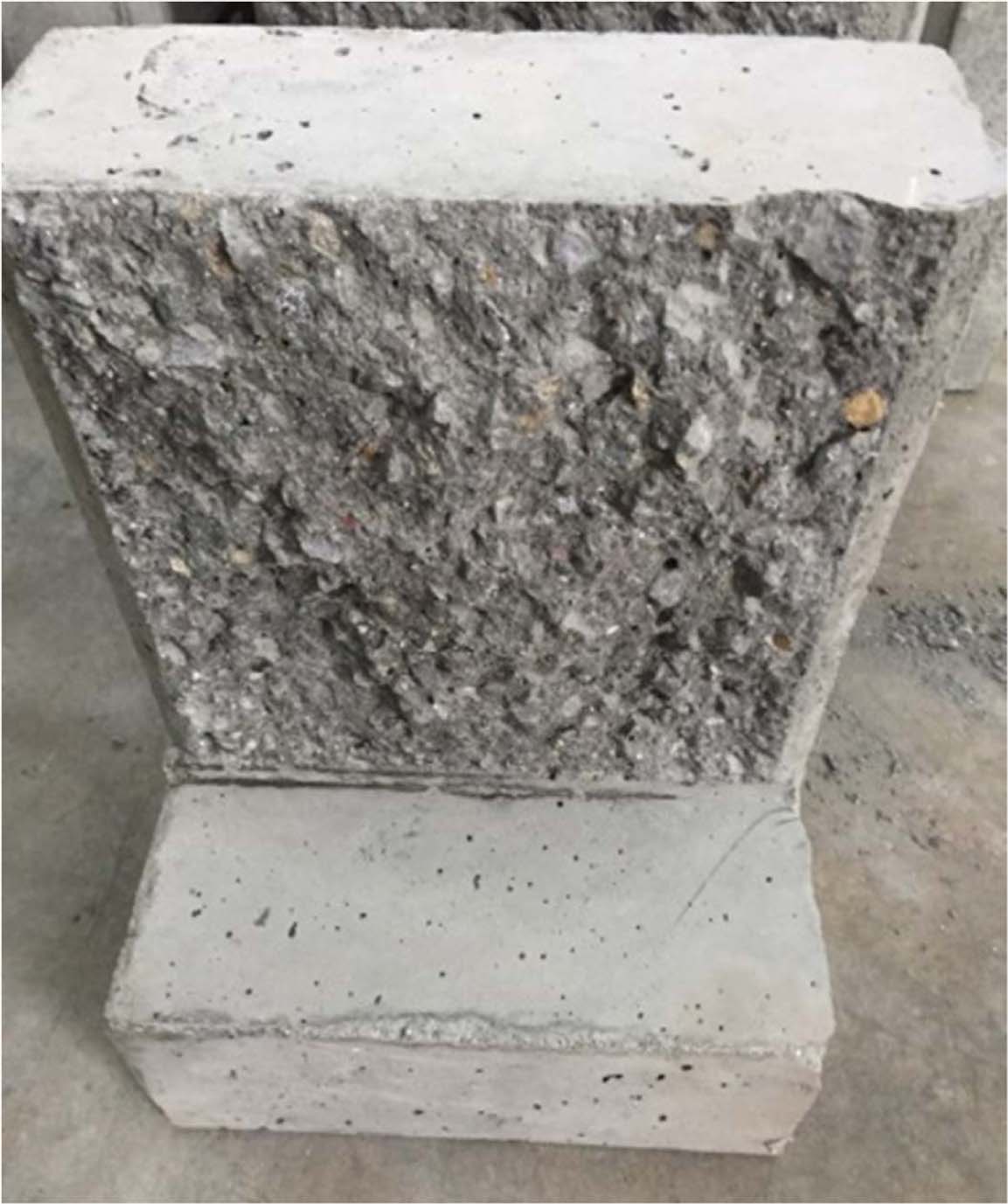
The shear strength test results revealed that failure occurred along the crack induction surface where pure shear force was applied for all the specimens. Fig. 14 shows the image of the failure surface of the specimen.
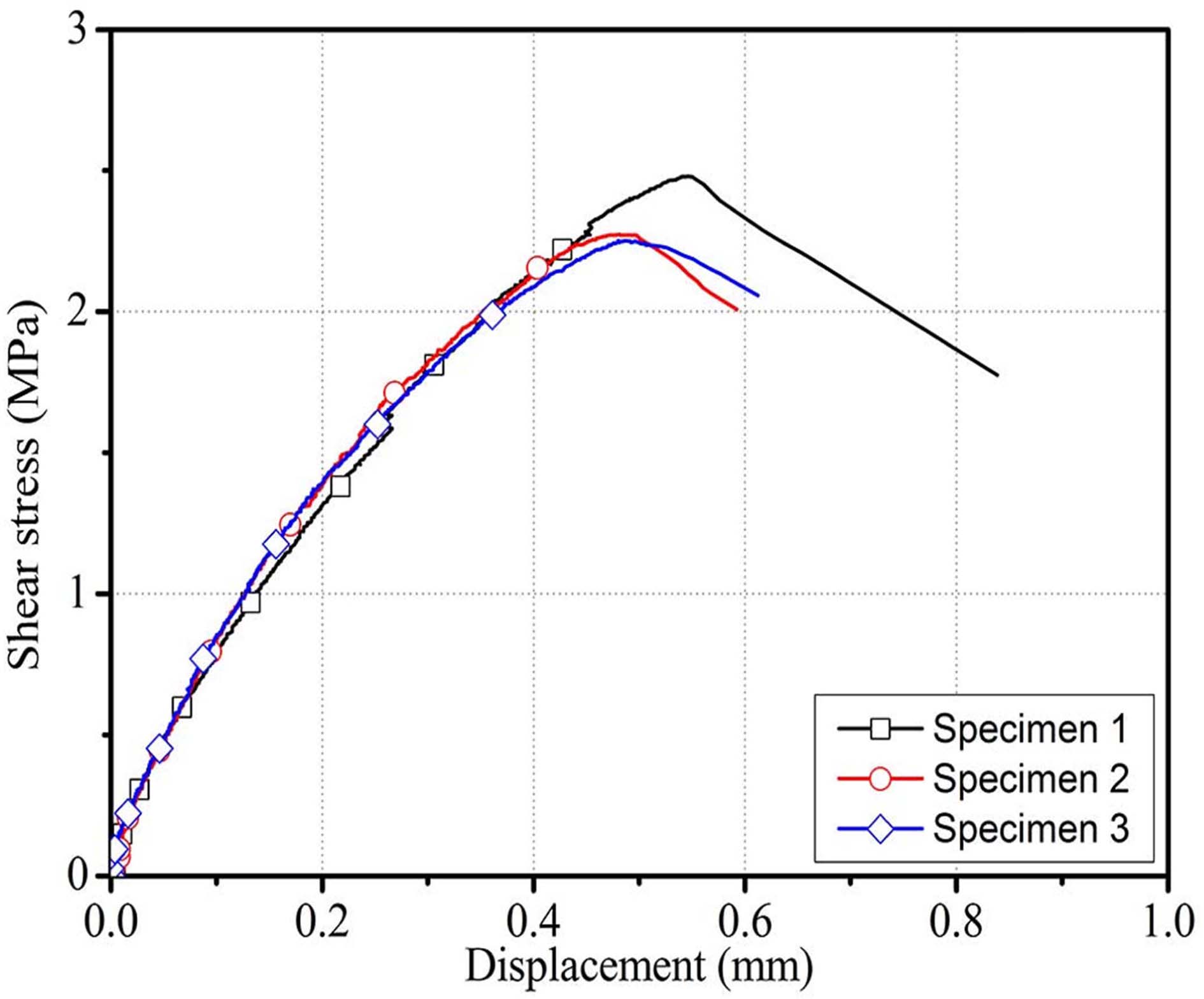
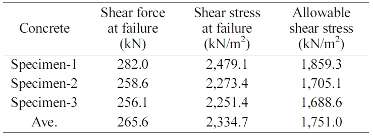
Fig. 15 and Table 8 reflect the results of the shear strength test of the model piles. Fig. 15 shows the shear stress-displacement graph obtained from the model piles, and Table 8 lists the final calculated shear stress and allowable shear stress values of the model piles. As given in the table, the shear strengths of the concrete specimens that utilized industrial by-products ranged from 256.1 to 282.0 kN. The displacement ranged from 0.48 to 0.54 mm when the load reached its peak. Moreover, the shear stress for the effective shear surface ranged from 2.25 to 2.48 MPa, with an average of 2.33 MPa. The allowable shear stress was determined by applying a strength sensitivity coefficient of 0.75. The determined average allowable bending stress was 1.81 MPa.
|
Fig. 13 Shear strength specimen plan. |
|
Fig. 14 Failure surface of the shear specimen. |
|
Fig. 15 Shear stress-displacement relationship of the model piles. |
Numerical analysis was conducted using the physical properties obtained from the model pile experiments to evaluate the field applicability of the developed new-type pile material. The application site was determined to be the line OO site, where the embankment pile structure was being installed as a test, among the actual railway construction sections. The results of the model pile experiments were applied as the physical properties of the piles applied for the analysis. Table 9 gives the input properties of the new-type cast-in-place pile.
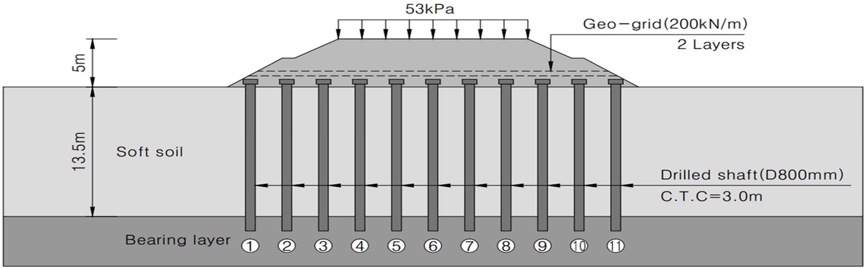
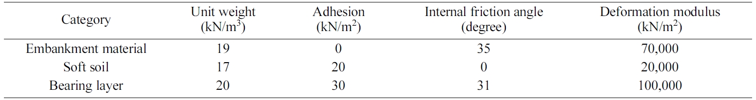
A cross section with a 5.0 m embankment height and a 13.5 m soft layer thickness was used as the cross section for numerical analysis, as shown in Fig. 16. The soil properties of each layer were summarized in Table 10. Total 11 piles were placed in the cross section with a center-to-center spacing (C.T.C) of 3.0 m, and two layers of geosynthetics were applied to the top of the piles. A PET mat with a unit weight of 6 kN/m3 and a tensile strength of 200 kN/m2 was applied as the geosynthetic. A top load of 53 kPa was applied considering the track load (17 kPa) and train load (36 kPa).
|
Fig. 16 Analysis cross section of the embankment piles in the railway section. |
|
Table 9 Numerical analysis input properties of the new-type cast-in-place pile. |

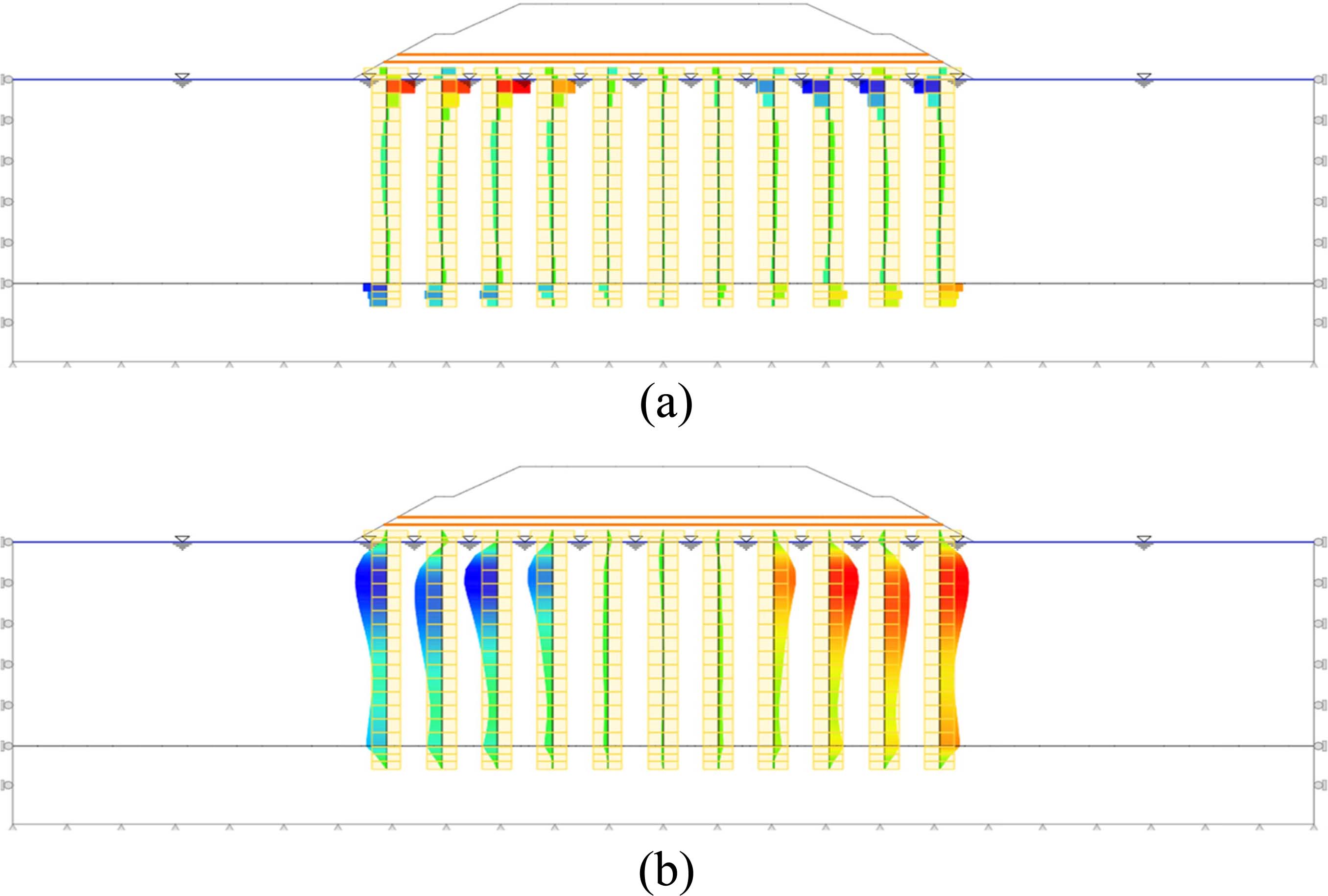
For the numerical analysis to examine the safety of the new-type cast-in-place pile material for embankments, Soilworks from MIDAS, a finite element analysis software program, was used to model the planned cross section. As a result of the numerical analysis, the shear force and moment distributions according to the depth of the new-type cast-in-place pile were obtained as shown in Fig. 17. The piles at the center of the embankment mainly played the role of supporting the vertical load, but the piles at the outer sections of the embankment also played the role of resisting the displacement caused by the force acting on the slope. Therefore, the maximum moment, 81.2 kN·m, and maximum shear force, 56.5 kN, occurred at piles 1 and 11.
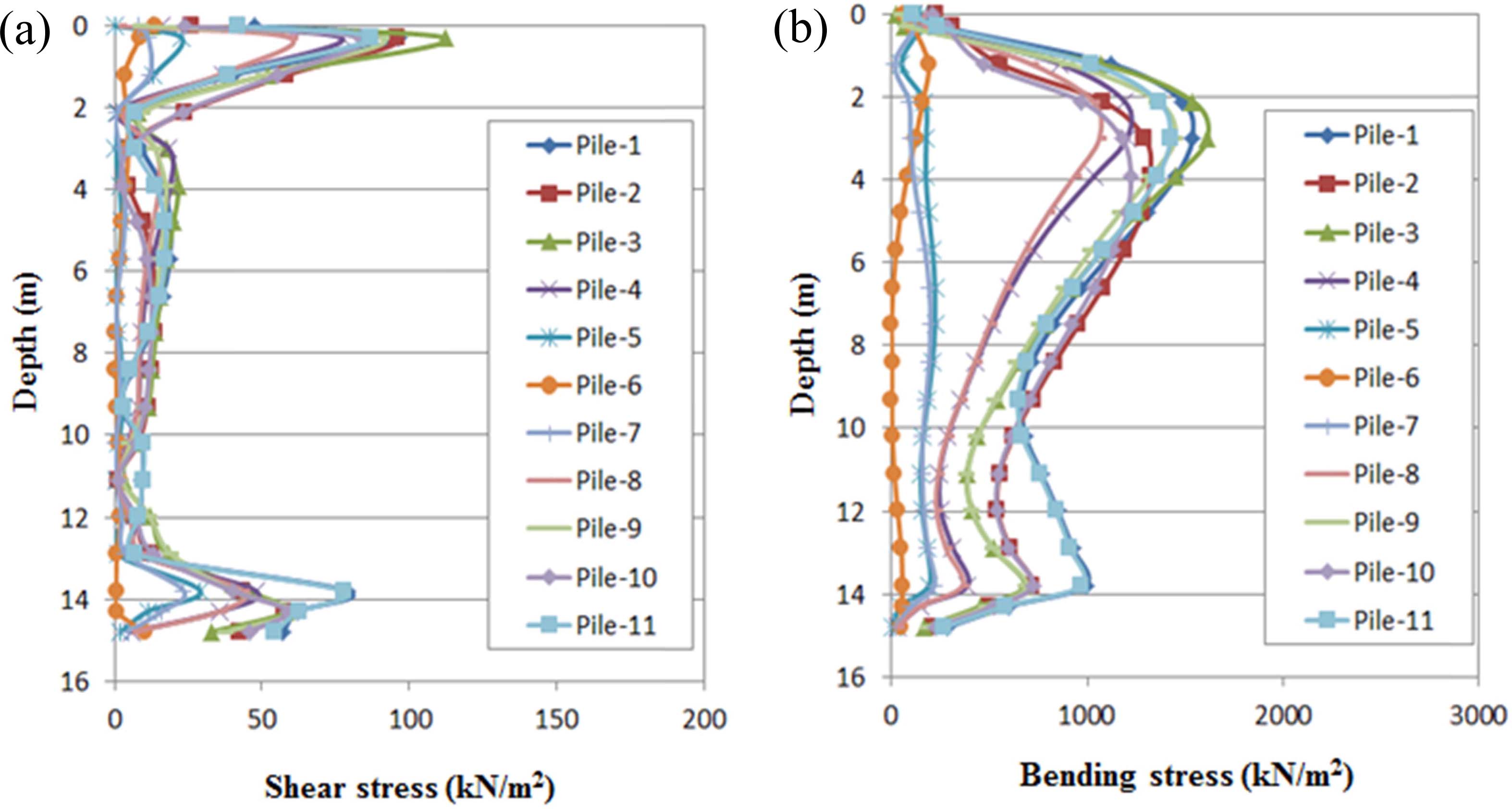
The shear stress of each pile was obtained by dividing the maximum shear force by the cross section of the pile, and the bending stress was obtained by dividing the moment of each pile by the section modulus. The obtained shear stress and bending stress were compared with the allowable shear stress and allowable bending stress of the new-type cast-in-place pile for embankments derived through the model pile experiments as shown in Fig. 18.
The maximum shear stress of the new-type cast-in-place pile was found to be 112.4 kN/m2, which was lower than the allowable shear stress of 1,751.0 kN/m2 obtained through the model pile experiments. Moreover, the maximum magnitude of the pure bending stress acting on the new-type cast-in-place pile was found to be 1,614.8 kN/m2, which was lower than the allowable bending stress of 1,809.3 kN/m2. These results indicate that the new-type cast-in-place pile material that utilizes industrial by-products can be used as an embankment pile material.
|
Fig. 17 Numerical analysis results (shear force and moment distributions according to depth). (Stage 5): (a) Shear force distribution for the piles according to depth and (b) Moment distribution for the piles according to the depth. |
|
Fig. 18 Numerical analysis results (shear stress and bending stress according to depth). (Stage 6): (a) Shear stress according to the depth and (b) Bending stress according to the depth. |
In this study, a new type of pile material with high economic efficiency and reliability was developed using relatively low-cost industrial by-products as alternative materials, and its applicability was evaluated through strength experiments and field application numerical analysis with a series of model piles.
(1) From the wide range of industrial by-products available, fly ash and blast furnace slag were chosen for use as binders instead of cement, and recycled aggregate was used as a filler instead of natural aggregate. To develop a pile material with high economic efficiency that meets the target design strength, strength experiments were performed under various conditions while the material replacement ratio was varied.
(2) The most economical concrete material that met the mixing strength requirement of 25 MPa required for embankment piles was found to be the F50R30S0 specimen composed of 50% fly ash and 30% recycled aggregate. An approximately 19% cost-saving effect was observed compared to the cost of existing cast-in-place concrete.
(3) As a result of conducting compressive strength tests by fabricating model piles with the developed new type of pile material, the target design strength of the embankment pile material was met. Moreover, the allowable bending stress and allowable shear stress of the new-type pile were obtained through the bending strength and shear strength tests.
(4) Numerical analysis was conducted for an embankment pile test installation site using the allowable bending stress and allowable shear stress obtained through model pile experiments. As a result, the shear stress and bending stress acting on the pile were within the allowable ranges, indicating that the new type of pile structure is effective for creating embankment piles.
This research was supported by a grant from R&D Program(PK1902A4) of the Korea Railroad Research Institute, Republic of Korea.
- 1. J. P. Magnan, in Proceedings of the Settlement ’94, June 1994, edited by A.T. Teung and G.Y. Félio (American Society of Civil Engineers Press, 1994) p.77-91.
- 2. S.L. Shen, J.C. Chai, Z.S. Hong, and F.X. Cai, Geotext. Geomembr. 23[6] (2005) 463-485.
-

- 3. W.J. Hewlett, and M. F. Randolph, Ground Engineering. 22[3] (1988) 12-18.
- 4. B.K. Low, S. K. Tang, and V. Chao, J. Geotech. Eng. 120[11] (1994) 1917-1938.
-
- 5. D. Zaeske, Zur Wirkungsweise von Unbewehrten und bewehrten Mineralischen Tragschichten über Pfahlartigen Gründungselementen (2001) 14-38
- 6. C. Heitz, in Bodengewölbe unter ruhender und nichtruhender Belastung bei Berücksichtigung von Bewehrungseinlagen aus Geogittern (2006) 6-20.
- 7. Y.M. Chen, W.P. Cao, and R.P. Chen, Geotext. Geomembr. 26[2] (2008) 164-174.
- 8. A. Arulrajah, A. Abdullah, M.W. Bo and M. Leong, Proc. Inst. Civ. Eng. Ground Improv.168[1] (2015) 3-13.
-
- 9. KCI, in “Concrete structure design code” (Korea Concrete Institute Press, 2012) 53.
- 10. J.J. Kim, J. Korea Inst. Build. Constr. 14[3] (2014) 223-229.
-
- 11. Korean Standards, KS F 2403 (2014) 1-15.
- 12. Korean Standards, KS F 2405 (2010) 1-6.
- 13. Korean Standards, KS F 2408 (2016) 1-13.
- 14. K.W. Kal, K.S. Kim, D.H. Lee, J.H. Hwang, and Y.H. Oh, J.Korea Inst. Struct. Maint. Insp. 14[3] (2016) 160-170.
 This Article
-
2019; 20(S1): 113-124
Published on Jul 20, 2019
- Received on Dec 9, 2018
- Revised on Jun 10, 2019
- Accepted on Jul 10, 2019
Services
- Abstract
introduction
development of the new type of pile material
model pile experiment for evaluating the strength of the new type of pile
conclusions
- Acknowledgements
- References
- Full Text PDF
Shared
Correspondence to
- Mintaek Yoo
-
Railroad Structure Research Team, Korea Railroad Research Institute, 176 Cheoldobangmulgwan-ro, Uiwang-si, Gyeonggi-do, 16105, Republic of Korea
Tel : +82-31-460-5490
Fax: +82-31-460-5034 - E-mail: thezes03@krri.re.kr
Clean-Energy Research Institute(CRI), Hanyang University, 222, Wangsimni-ro, Seongdong-gu, Seoul, 04763, Korea
E-mail: jcpr@hanyang.ac.kr